Efficiently-cooled LED street lamp

A technology of LED street lamps and LED light sources, which is applied to lampshades, lighting and heating equipment, and components of lighting devices, etc., can solve the problems of high maintenance costs, difficult heat dissipation of LED street lamps, and increased use costs of street lamps.

Active Publication Date: 2016-02-10
江苏国成光电科技有限公司
7 Cites 0 Cited by

AI-Extracted Technical Summary

Problems solved by technology

[0002] The design of LED street lamps in the prior art is usually designed to imitate the design of traditional street lamps, and multiple LED lamp beads are assembled in a module, so that the products produced by different manufacturers do not have universality and interchangeability, resulting in LED street lamps. Poor replacement and high maintenance cost, which indirectl...

Method used

[0018] The lamp body 2 includes a loam cake 3 and a transparent lower lid 4 arranged at the bottom of the loam cake 3. The loam cake 3 is fixed on the light pole 1, and the loam cake 3 and the transparent lower lid 4 are fixed by screws. The top of the upper cover 3 is provided with several frustum-shaped protrusions 30 . The top of the protrusion 30 is platform-shaped, which is used for connecting with the LED module 6 . The protrusion 30 is arranged in a frustu...

Abstract

The invention discloses an efficiently-cooled LED street lamp which comprises a lamp post, a lamp body and an LED light source. The lamp body comprises an upper cover and a transparent lower cover. The upper cover is fixed to the lamp post. The top of the upper cover is provided with a plurality of frustum-shaped protrusions. The top of each protrusion is provided with a screw hole and an annular protruding strip. The LED light source is composed of a plurality of independent LED modules. Each LED module comprises a cooler and an LED light emitting assembly fixedly arranged at the bottom of the cooler. Each cooler comprises a body and cooling fins arranged on the top of the body, wherein the bottom of the body is provided with a cylindrical boss and an annular groove, the boss is arranged at the center of the bottom of the body, the radial edge of the boss is provided with a thread matched with the screw hole, the corresponding light emitting assembly is arranged at the bottom of the boss, and the annular groove surrounds the radial edge of the boss and is matched with the corresponding annular protruding strip. The LED street lamp is good in universality and replaceability, low in maintenance cost and good in cooling effect.

Application Domain

Point-like light sourceLighting heating/cooling arrangements +4

Technology Topic

EngineeringLight source +1

Image

  • Efficiently-cooled LED street lamp
  • Efficiently-cooled LED street lamp
  • Efficiently-cooled LED street lamp

Examples

  • Experimental program(1)

Example Embodiment

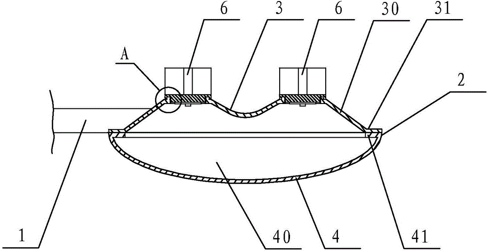
[0017] like Figure 1-4 The shown LED street lamp includes a lamp pole 1 , a lamp body 2 fixed on the lamp pole 1 and an LED light source arranged in the lamp body 2 .
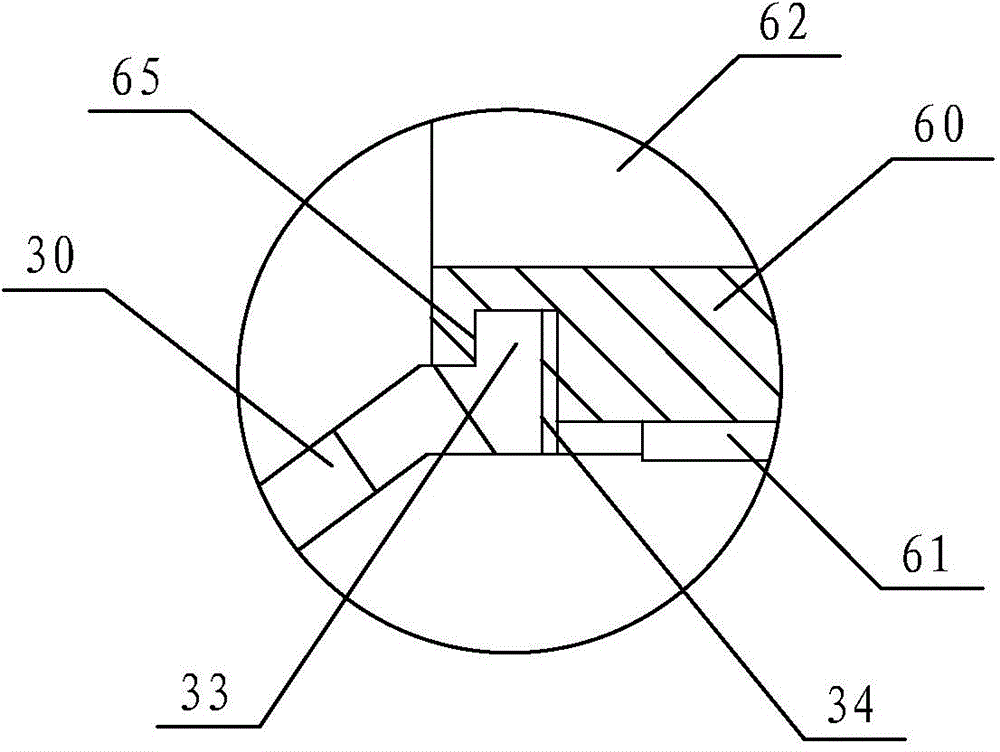
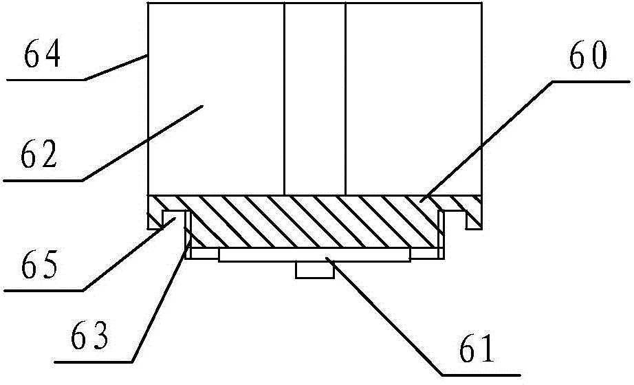
[0018] The lamp body 2 includes an upper cover 3 and a transparent lower cover 4 arranged at the bottom of the upper cover 3 , the upper cover 3 is fixed on the light pole 1 , and the upper cover 3 and the transparent lower cover 4 are fixed by screws. The top of the upper cover 3 is provided with several frustum-shaped protrusions 30 . The top of the protrusion 30 is platform-shaped, which is used for connecting with the LED module 6 . The protrusion 30 is arranged in a frustum shape to prevent rainwater from accumulating. To facilitate connection with the LED module 6 , a screw hole 34 penetrating through the upper cover 3 is provided on the top of each protrusion 30 . In order to prevent rainwater from seeping into the screw hole 34 , the top of each protrusion 30 is provided with an annular convex strip 33 surrounding the edge of the screw hole 34 , and the annular convex strip 33 mainly plays the role of preventing water seepage.
[0019] In order to facilitate the connection between the upper cover 3 and the transparent lower cover 4, the bottom edge of the upper cover 3 is provided with a first flange 31 extending outward, and the top edge of the transparent lower cover 4 is provided with a second flange 41 extending inward. The first flange 31 and the second flange 41 are paired and connected by screws. Preferably, grill holes for ventilation and drainage can also be provided on the end surface of the transparent lower cover 4 .
[0020] The power supply for converting the commercial power into the DC power required by the LED light source can be set in the lamp body 2 or in the light pole 1 , preferably in the light pole 1 .
[0021] The LED light source is composed of several LED modules 6 that can work independently, and the LED modules 6 emit light toward the ground. Each LED module 6 is configured corresponding to one protrusion 30 . Each LED module 6 includes a radiator 64 and an LED lighting assembly 61 fixed at the bottom of the radiator 64 . The heat sink 64 includes a cylindrical body 60 and heat dissipation fins 62 disposed on the top of the body 60 . The heat dissipation fins 62 radiate outward around the axis of the body 60 and are generally cylindrical. The bottom of the body 60 is provided with a cylindrical boss 63 and an annular groove 65 , the boss 63 is arranged at the center of the bottom of the body 60 , and the radial dimension of the boss 63 is smaller than that of the body 60 . The radial edge of the boss 63 is provided with a screw thread matched with the screw hole 34 , and the boss 63 is used to connect with the screw hole 34 . The light-emitting component 61 is disposed on the bottom of the boss 63 , and the annular groove 65 is arranged around the radial edge of the boss 63 and matched with the annular protrusion 33 . The LED lighting assembly 61 is fixed on the bottom of the main body 60 with heat-conducting glue.
[0022] When in use, the light-emitting assembly 61 of the LED module 6 faces downward; after the boss 63 is inserted into the screw hole 34 and tightened, the annular groove 65 is matched with the protrusion 30, and the LED module 6 is fixed on the upper cover 3, and Rainwater cannot enter in the screw hole 34 either.

PUM

no PUM

Description & Claims & Application Information

We can also present the details of the Description, Claims and Application information to help users get a comprehensive understanding of the technical details of the patent, such as background art, summary of invention, brief description of drawings, description of embodiments, and other original content. On the other hand, users can also determine the specific scope of protection of the technology through the list of claims; as well as understand the changes in the life cycle of the technology with the presentation of the patent timeline. Login to view more.
Why Eureka
Try Eureka