A permanent magnet servo motor sticky magnet steel gluing device and gluing method

A technology of permanent magnet servo motor and gluing device, which is applied in the field of magnetic steel, can solve the problems of high cost, high design requirements of magnetic head, brittle texture, etc., and achieve the effect of fast gluing and convenient gluing work

Active Publication Date: 2018-05-22
SHANGHAI LEIZHI MOTOR
View PDF4 Cites 1 Cited by
  • Summary
  • Abstract
  • Description
  • Claims
  • Application Information

AI Technical Summary

Problems solved by technology

[0006] These two solutions have certain defects in the actual use process, and their shortcomings are mainly reflected in: For the first method, the magnetic steel has strong magnetic properties and a very brittle texture, which is very inconvenient for workers to operate, and it is relatively easy to break the magnetic steel;
[0007] For the second method, the post-magnetization of the motor rotor has high requirements on the design of the magnetization head and high cost; and the consistency of the magnetic properties of the magnetized steel is not very good

Method used


Image

  • A permanent magnet servo motor sticky magnet steel gluing device and gluing method
  • A permanent magnet servo motor sticky magnet steel gluing device and gluing method
  • A permanent magnet servo motor sticky magnet steel gluing device and gluing method

Examples


Embodiment Construction

[0034] In order to make the technical means, creative features, goals and effects achieved by the present invention easy to understand, the present invention will be further described below in conjunction with specific illustrations.

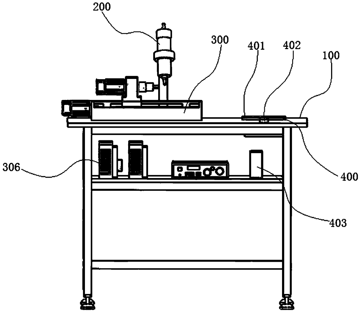
[0035] see figure 1 , which is a schematic structural view of the permanent magnet servo motor sticking magnetic steel gluing device in this example. The gluing device is mainly equipped with four parts: a stand 100 , a pneumatic gluing device 200 , a rotor clamping and driving device 300 , and a control mechanism 400 .

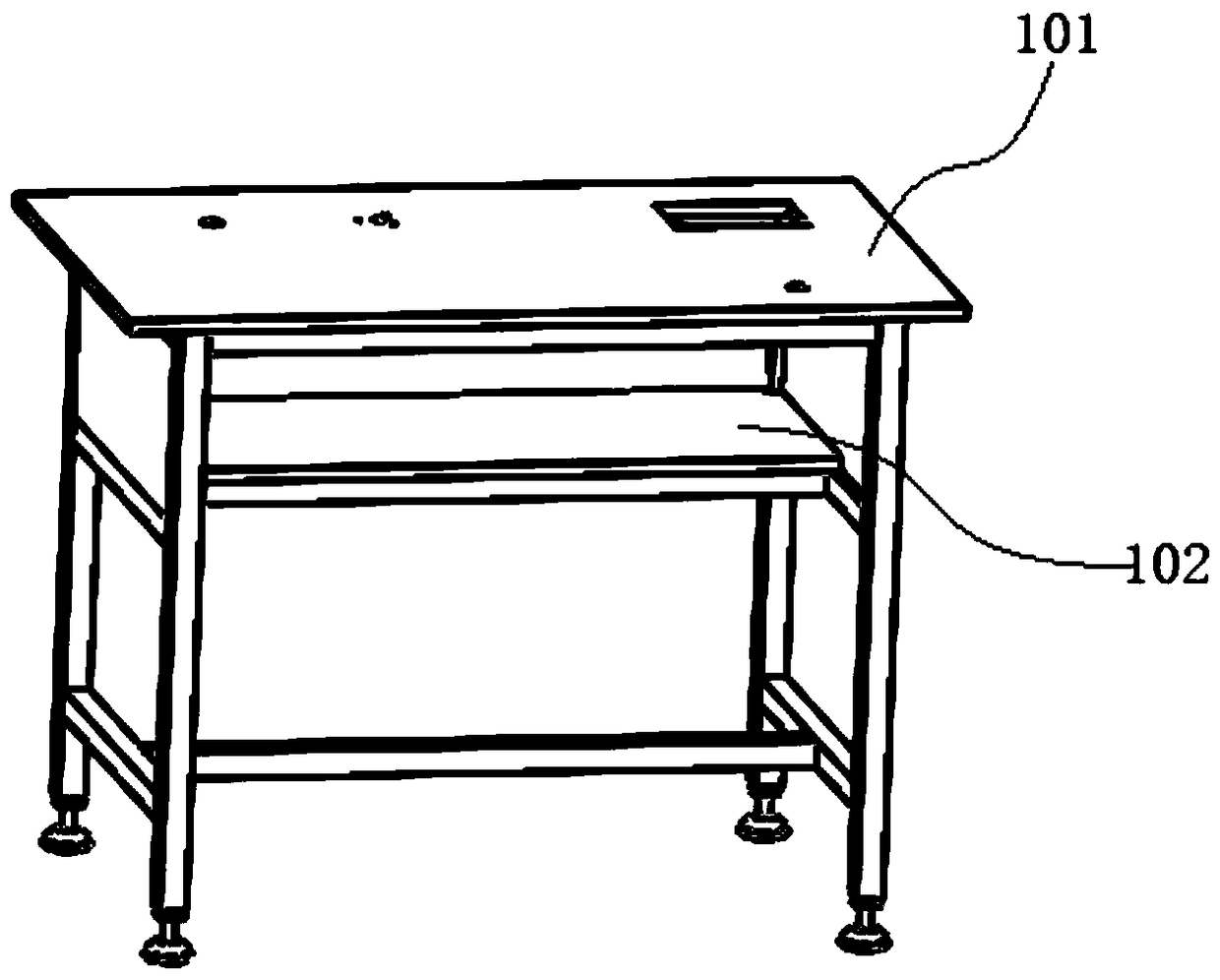
[0036] Wherein, the equipment stand 100 is used as the main body frame of the whole gluing device, and is used for carrying other components.

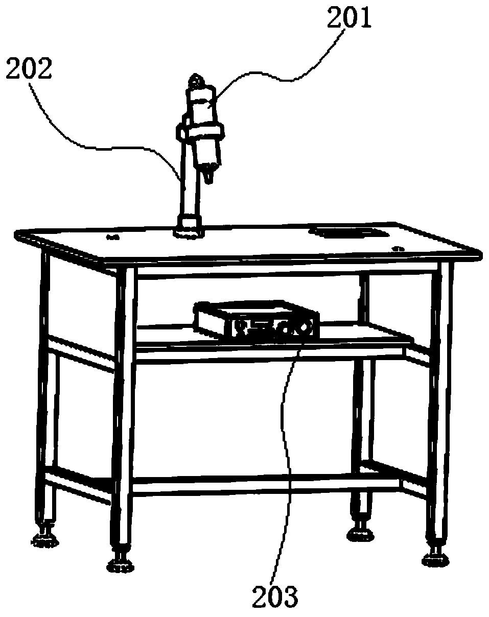
[0037] Pneumatic gluing device 200 is the whole gluing action part. The pneumatic gluing device 200 is integrally arranged on the operating table of the equipment stand 100, and the rotor 500 driven by the rotor clamping and driving device 300 (see Figure 5 ) surface with glue.

[0...


PUM


Abstract

The invention discloses a permanent magnet servo motor sticky magnetic steel gluing device and a gluing method. The device mainly includes: an equipment stand, an air pressure gluing device, a rotor clamping and driving device and a control mechanism, and an air pressure gluing device. On the equipment stand; the rotor clamping and driving device is set on the equipment stand, and the clamped rotor is driven to move spirally relative to the air pressure gluing device, so that the surface of the rotor passes through the air pressure gluing device in turn; the control mechanism controls the connection of the air pressure gluing device The device and the rotor clamping and driving device are controlled to work together. When applying glue, the control mechanism firstly determines the trajectory of glue coating on the surface of the rotor to be glued, and then controls the rotor clamping and driving device based on the trajectory, and the rotor clamping and driving device drives the rotor to be coated to rotate and move, so that the rotor to be coated The surface of the rotor is glued sequentially through the pneumatic glue coating device according to the determined glue coating track. This scheme can realize the rapid glue application when the permanent magnet servo motor sticks the magnetic steel.

Description

technical field [0001] The invention relates to a magnetic steel in a permanent magnet servo motor, in particular to a magnetic steel adhesion technology. Background technique [0002] As the core component of permanent magnet motor, magnet steel plays a decisive role in the performance of permanent magnet motor. [0003] At present, there are two main methods of sticking magnetic steel for permanent magnet motors: [0004] 1. Manually operated directly by workers, the side of the magnetic steel filled with magnets is glued to the surface of the motor rotor by applying glue; [0005] 2. First, glue the unmagnetized magnetic steel to the surface of the rotor by smearing glue, and then magnetize the rotor as a whole. [0006] These two solutions have certain defects in the actual use process, and their shortcomings are mainly reflected in: for the first method, the magnetic steel has strong magnetic properties and a very brittle texture, which is very inconvenient for worker...

Claims


Application Information

Patent Timeline
Patent Type & Authority Patents(China)
IPC IPC(8): H02K15/03H02K15/12
Inventor 荆红民李忠萍段宗才徐军
Owner SHANGHAI LEIZHI MOTOR
Why Eureka
Try Eureka