Switch By-pass circuit

A switch and switch chip technology, applied in the direction of data exchange network, electrical components, digital transmission system, etc., can solve the problems of train data interruption, power supply damage, and inability to cross-level transmission, so as to reduce maintenance expenditure, reduce failure rate, The effect of improving stability

Inactive Publication Date: 2016-02-10
TIANJIN BEIHAI COMM TECH
View PDF0 Cites 3 Cited by
  • Summary
  • Abstract
  • Description
  • Claims
  • Application Information

AI Technical Summary

Problems solved by technology

[0002] like figure 1 As shown, it is the network wiring method of the whole train of the PIS system, including 2 cabs, 6 passenger compartments, 1, 2, 3, and 4 are marked as M12 network interfaces, and train data, including broadcast data, media data, and monitoring data, pass through the switch Transmission, from the cab to the passenger compartment or from the passenger compartment to the cab, is a level-by-level transmission. For example, when transmitting data from the cab 1 to the passenger compartment 2, it must pass through the passenger compartment 1 and cannot be transmitted across levels.
According to field data, the failure rate of switches in actual applications is relatively high, mostly due to power supply damage, such as figure 1 As shown, although redundancy is considered in the design and two links are designed, when one link fails, the other link can still work without affecting the functions of the entire system, but the power failure of the switch will cause all functions of the switch Failure, which in turn causes the train data to be interrupted at the fault point of the switch, affecting the function of the entire train

Method used


Image

  • Switch By-pass circuit
  • Switch By-pass circuit

Examples


Embodiment Construction

[0010] Specific embodiments of the invention will be described in detail below in conjunction with the accompanying drawings.

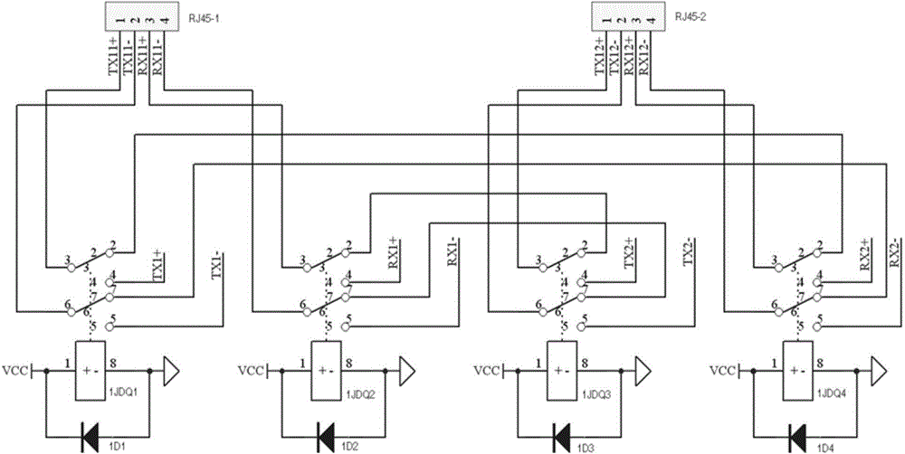
[0011] Such as figure 2 As shown, a switch By-pass circuit includes two RJ45 network interfaces and four relays, the RJ45 network interfaces include TX+, TX-, RX+ and RX-, the 1 pin of the RJ45-1 network interface is connected to the relay 1JDQ1 The 3rd contact of the RJ45-1 network interface is connected to the 6th contact of the relay 1JDQ1, the 3rd pin of the RJ45-1 network interface is connected to the 3rd contact of the relay 1JDQ2, the RJ45-1 network interface Pin 4 of the RJ45-2 network interface is connected to the sixth contact of the relay 1JDQ2, pin 1 of the RJ45-2 network interface is connected to the third contact of the relay 1JDQ3, pin 2 of the RJ45-2 network interface is connected to the sixth contact of the relay 1JDQ3 The 3 pins of the RJ45-2 network interface are connected to the 3rd contact of the relay 1JDQ4, the 4 pins of the R...


PUM


Abstract

The invention provides a switch By-pass circuit including two RJ45 network interfaces and four relays (1JDQ1 to 1JDQ4). A first pin and a second pin of RJ45-1 are connected with a third contact and a sixth contact of 1JDQ1 respectively. A third pin and a fourth pin of RJ45-1 are connected with a third contact and a sixth contact of 1JDQ2 respectively. A first pin and a second pin of RJ45-2 are connected with a third contact and a sixth contact of 1JDQ3 respectively. A third pin and a fourth pin of RJ45-2 are connected with a third contact and a sixth contact of 1JDQ4 respectively. A second contact and a seventh contact of 1JDQ1 are connected with a second contact and a seventh contact of 1JDQ4 respectively. A second contact and a seventh contact of 1JDQ2 are connected with a second contact and a seventh contact of 1JDQ3 respectively. The switch By-pass circuit ensures that a single-point fault does not diffuse, improves the stability of the whole system, reduces the fault rate of the system, and meanwhile reduces the maintenance expenditure of companies.

Description

technical field [0001] The invention belongs to the field of circuit design, and in particular relates to a switch By-pass circuit. Background technique [0002] Such as figure 1 As shown, it is the network wiring method of the whole train of the PIS system, including 2 cabs, 6 passenger compartments, 1, 2, 3, and 4 are marked as M12 network interfaces, and train data, including broadcast data, media data, and monitoring data, pass through the switch The transmission, from the cab to the passenger compartment or from the passenger compartment to the cab, is a level-by-level transmission. For example, to transmit data from the cab 1 to the passenger compartment 2, it must pass through the passenger compartment 1 and cannot be transmitted across levels. According to field data, the failure rate of switches in practical applications is relatively high, mostly due to power supply damage, such as figure 1 As shown, although redundancy is considered in the design and two links a...

Claims


Application Information

Patent Timeline
Patent Type & Authority Applications(China)
IPC IPC(8): H04L12/939
Inventor 王洪江
Owner TIANJIN BEIHAI COMM TECH
Why Eureka
Try Eureka