
Quick molding punch

A forming punch, rapid technology, applied in the direction of forming tools, applications, household appliances, etc., can solve the problems of low production efficiency and numerous processes, and achieve the effect of improving production efficiency

Inactive Publication Date: 2016-03-02
天津市怡润包装容器有限责任公司
View PDF0 Cites 3 Cited by
  • Summary
  • Abstract
  • Description
  • Claims
  • Application Information

AI Technical Summary

Problems solved by technology

[0002] In the existing technology, the stamping of round can lids with rolled edges often requires three processes of cutting, stamping the edges, and stamping and flanging. The process is numerous and the production efficiency is low.

Method used


Image

  • Quick molding punch
  • Quick molding punch
  • Quick molding punch

Examples


Embodiment Construction

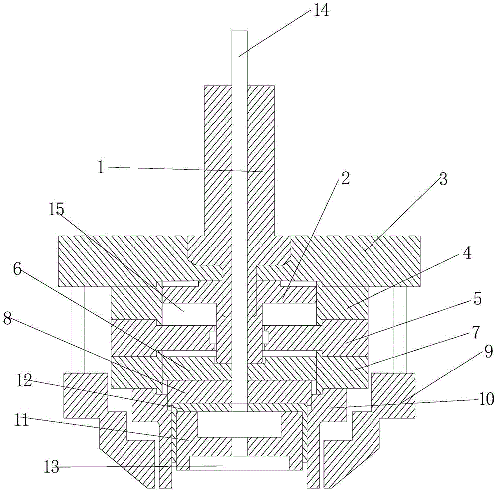
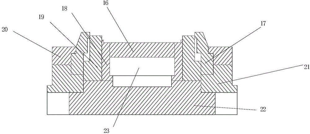
[0026] As shown in the figure, the present invention provides a rapid prototyping punch, including an upper mold unit and a lower mold unit, and the upper mold unit includes a mold handle 1, an upper mold plate 3, a first cylinder block 4, a second cylinder block 7, and a cylinder Separator body 5, first piston 2, second piston 6, fixed plate 8, punch and die 10, beating plate 12, upper mold core 11 and beating rod 14;

[0027] The mold handle 1 is fixed on the upper mold plate 3, the first cylinder block 4 is fixed on the bottom of the upper mold plate 3, the cylinder partition body 5 is fixed on the bottom of the first cylinder block 4, and the second cylinder block 7 is fixed on the cylinder partition body 5 bottom;

[0028] There is a first piston 2 in the air chamber of the first cylinder body 4, and the first piston 2 can move up and down in the air chamber of the first cylinder body 4, and there is a second piston 6 in the air chamber of the second cylinder body 7, and ...


PUM


Abstract

The invention provides a quick molding punch which comprises an upper die unit and a lower die unit. The upper die unit is of the structure with a cylinder block and a piston. An upper die and a lower die are provided with an upper blade edge and a lower blade edge respectively, and cutting of round sheet iron, stamping of the edge of a can cover and hemming of the edge of the can cover are simultaneously carried out in the die combining process. The quick molding punch has the beneficial effects that the one-time cutting and stamping molding of the can cover is achieved, and production efficiency is high.

Description

technical field [0001] The invention relates to a rapid forming punch. Background technique [0002] In the prior art, stamping of round can lids with curling usually requires cutting, stamping the edge, and stamping and flanging three processes to complete, which has many processes and low production efficiency. Contents of the invention [0003] The problem to be solved by the present invention is to provide a quick-forming punch, which overcomes the deficiencies in the prior art. [0004] In order to solve the above-mentioned technical problems, the technical solution adopted in the present invention is: the rapid prototyping punch includes an upper mold unit and a lower mold unit, and the upper mold unit includes a die handle, an upper mold plate, a first cylinder block, a second cylinder block, a cylinder Separator body, first piston, second piston, fixed plate, convex and concave dies, beating plate, upper mold core and beating rod; [0005] The mold handle is fixe...

Claims


Application Information

Patent Timeline
IPC IPC(8): B21D37/10B21D35/00B21D51/44
Inventor 金允通
Owner 天津市怡润包装容器有限责任公司
Learn More