A low-power door lock button

A door lock and button technology, which is applied in the field of low-power door lock buttons, can solve the problems of large power consumption of buttons, and achieve the effects of reducing power consumption, reducing costs, and quickly switching on and off

Inactive Publication Date: 2017-12-15
HEFEI TIANZHI TECH DEV
View PDF7 Cites 0 Cited by
  • Summary
  • Abstract
  • Description
  • Claims
  • Application Information

AI Technical Summary

Problems solved by technology

[0003] The technical problem to be solved by the present invention is to provide a low-power door lock button to solve the problem of large power consumption of the existing door lock button, so as to prolong the service life of the battery device and save costs

Method used


Image

  • A low-power door lock button
  • A low-power door lock button
  • A low-power door lock button

Examples


Embodiment Construction

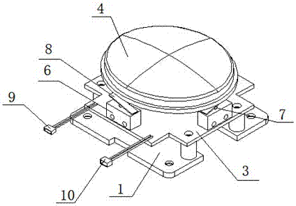
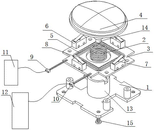
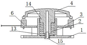
[0013] As shown in Figures 1-3, a low-power door lock button includes a base 1, a return spring 2 fixed on the base 1, a PCB board 3, a button head 4 connected to the return spring 2, and a button set on the PCB. The induction coil 5 and the micro switch 6 on the board 3, the top end surface of the micro switch 6 is provided with a contact point 7, and the top end surface of the micro switch 6 is connected with a shrapnel 8, and the shrapnel 8 is located on the top of the micro switch 6 On the end face, and one end is connected to the top end face of the micro switch 6, the button head 4 squeezes the shrapnel 8, the PCB board 3 is respectively connected to the first socket 9 and the second socket 10 through wires, and the external battery device 11 is connected to the first The socket 9 is connected, and the external door lock main control board 12 is connected with the second socket 10; the upper end surface of the base 1 is provided with a circular tube-shaped positioning sea...


PUM


Abstract

The invention discloses a low-power door lock button, which includes a base, a return spring fixed on the base, a PCB board, a button connected to the return spring, an induction coil and a micro switch arranged on the PCB board, and the induction The coil is connected to the external door lock main control board, the PCB board is connected to the external battery device, a contact point is provided on the top end surface of the micro switch, and a shrapnel is connected to the top end surface of the micro switch, and the button The head squeezes the shrapnel. The present invention is provided with a micro switch, and when the button head is pressed, the micro switch starts, so that the PCB board connected to the battery device is energized and activated to reach the working state; when the button head is not pressed, the micro switch is turned off, and the PCB The board is not powered, so that the door lock button is temporarily in a dormant state, thereby reducing power consumption, prolonging the service life of the door lock and battery device, and achieving the function of reducing costs.

Description

technical field [0001] The invention relates to the field of door locks, in particular to a low power consumption door lock button. Background technique [0002] The door lock button, as the name suggests, is the button that realizes the start of the door lock. It is connected to the main control board of the electronic door lock, and when pressed, it starts the electronically controlled lock cylinder of the electronic door lock and opens the door. However, the existing door lock button is always in a power supply state during use, so as to ensure that the start operation can be passed to the electronically controlled lock cylinder of the door lock when pressed, so as to realize the linkage of the door lock. Because the door lock button is always in the power supply state, the power consumption is large, and the usage of the battery device is too large, which reduces the service life of the battery device. Contents of the invention [0003] The technical problem to be sol...

Claims


Application Information

Patent Timeline
Patent Type & Authority Patents(China)
IPC IPC(8): E05B47/00E05B17/22E05B15/00
Inventor 余晖陈玉梅王勉赵宁赵靖郭良杨慧刘瑞
Owner HEFEI TIANZHI TECH DEV
Why Eureka
Try Eureka