A mechanical gripper

A manipulator and gripper technology, applied in the field of picking and unloading devices, can solve the problems of high labor cost and low manual handling efficiency, and achieve the effects of improving grasping quality, stable and easy control of force output, and ensuring stability.

Active Publication Date: 2018-04-10
WUHU HENGXIN AUTO INTERIOR TRIM COMPANY
View PDF6 Cites 0 Cited by
  • Summary
  • Abstract
  • Description
  • Claims
  • Application Information

AI Technical Summary

Problems solved by technology

[0007] The purpose of the present invention is to overcome the deficiencies in the prior art, such as low manual handling efficiency and high labor cost when the product is manually taken out during the injection molding process, and provides a manipulator gripper, which can improve workshop production by adopting the technical solution. Efficiency and the level of workshop mechanization, and simple structure, low cost

Method used


Image

  • A mechanical gripper
  • A mechanical gripper
  • A mechanical gripper

Examples


Embodiment 1

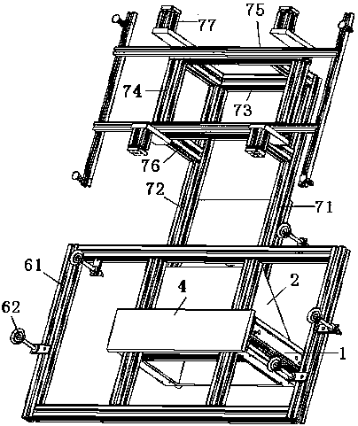
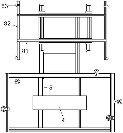
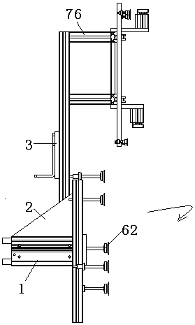
[0027] combine figure 1 , figure 2 and image 3 , a kind of manipulator gripper of the present embodiment, comprises the first gripper, the second gripper, the fixed plate 4 and the first connecting rod 5, and it also includes the air cylinder 1, the triangular rib 2 and the connecting block 3, the fixed plate 4 A cylinder 1 is arranged symmetrically at both ends. The piston rod of the cylinder 1 is fixedly connected with the fixed plate 4 and is perpendicular to the fixed plate 4. The fixed plate 4 is fixedly connected with the first gripper through the first connecting rod 5. The cylinder barrel of the above-mentioned cylinder 1 It is fixedly connected with the triangular rib 2, and the triangular rib 2 is fixedly connected with the second gripper. The second gripper is provided with a connecting block 3, and the plane where the second gripper is located is parallel to the plane where the first gripper is located.

[0028] The first gripper comprises a gripper body, and t...


PUM


Abstract

The invention discloses a manipulator gripping tool, and belongs to the field of material taking and putting devices. The manipulator gripping tool comprises a first gripping tool body, a second gripping tool body, a fixing plate, a first connecting rod, air cylinders, a triangular rib and a connecting block. The air cylinders are symmetrically arranged at the two ends of the fixing plate. Piston rods of the air cylinders are fixedly connected with the fixing plate and perpendicular to the fixing plate. The fixing plate is fixedly connected with the first gripping tool body through the first connecting rod. Cylinder barrels of the air cylinders are fixedly connected with the triangular rib which is fixedly connected with the second gripping tool body. The second gripping tool body is provided with the connecting block. The plane where the second gripping tool body is located is parallel to the plane where the first gripping tool body is located. According to the technical scheme, the production efficiency and the mechanization level in a workshop can be improved, moreover, the structure is simple, and the cost is low.

Description

technical field [0001] The invention relates to a pick-and-place device, more specifically, to a manipulator gripper. Background technique [0002] At present, with the continuous improvement of plastic materials and their processing technology, multi-layer composite board technology, glass fiber felt technology, long fiber molding technology and long fiber injection molding technology have been widely used to manufacture front-end brackets. Recently, more and more front-end brackets adopt plastic / metal composite structure, which makes full use of the performance advantages of plastic and metal, can make the best use of everything and integrate it cleverly, so as to realize the optimization of functions and the minimization of cost and weight . [0003] At present, the sheet metal needs to be manually placed into the mold before the injection molding of the front-end bracket, and the product is manually taken out after the injection molding is completed. However, the manual...

Claims


Application Information

Patent Timeline
Patent Type & Authority Patents(China)
IPC IPC(8): B29C45/17B29C45/14B29C31/08B29C45/42B25J15/06
CPCB25J15/06B29C45/14008B29C45/4225B29C2045/425
Inventor 周超群谢友阔陈明陈昭张杰
Owner WUHU HENGXIN AUTO INTERIOR TRIM COMPANY
Why Eureka
Try Eureka