Adjusting method for air intake flow of supercharger compressor

A technology of air intake flow and adjustment method, which is applied to machines/engines, mechanical equipment, combustion engines, etc., and can solve the problems of complex control and high cost.

Active Publication Date: 2016-03-09
中国船舶集团有限公司第七一一研究所
View PDF5 Cites 0 Cited by
  • Summary
  • Abstract
  • Description
  • Claims
  • Application Information

AI Technical Summary

Problems solved by technology

Since the geometric section of the nozzle ring is sensitive to the boost ratio, a complex control system is required to achieve precise adjustment of the geometric section of the nozzle ring, which is complex and expensive to control

Method used


Image

  • Adjusting method for air intake flow of supercharger compressor
  • Adjusting method for air intake flow of supercharger compressor
  • Adjusting method for air intake flow of supercharger compressor

Examples


Embodiment Construction

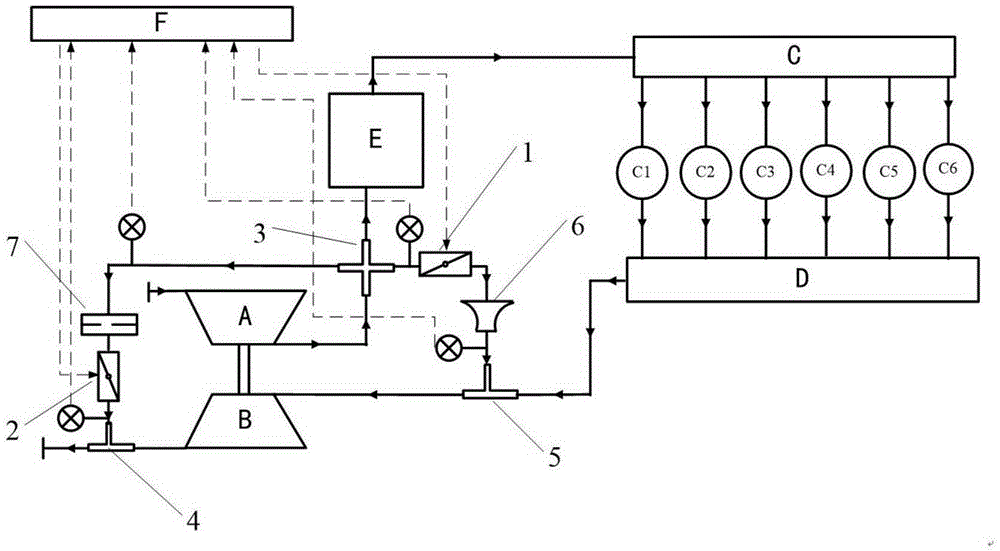
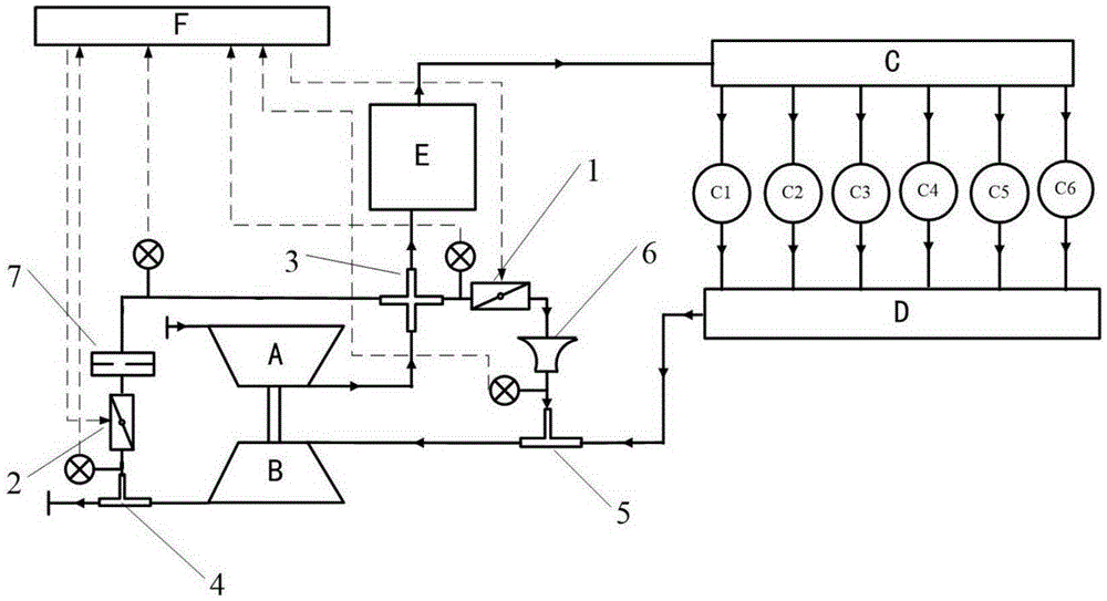
[0025] A preferred embodiment of the present invention is figure 2 As shown in the figure, A is the compressor of the supercharger, B is the turbine of the supercharger, C is the intake manifold of the internal combustion engine, D is the exhaust manifold of the internal combustion engine, E is the air cooler, and F is the control system.

[0026] Compressor inlet flow adjustment device includes:

[0027] (1) The intake and exhaust bypass pipeline between the compressor outlet and the turbine inlet of the supercharger is arranged, and a butterfly valve 1 (first control valve) is arranged on the intake and exhaust bypass pipeline to control the compressor outlet to For the flow rate at the inlet of the turbine, the butterfly valve 1 can be an on-off valve or an adjustable valve;

[0028] (2) The intake bypass air discharge pipeline between the compressor outlet and the turbine outlet of the supercharger is arranged, and a butterfly valve 2 (second control valve) is arranged o...


PUM


Abstract

The invention discloses an adjusting method for the air intake flow of a supercharger compressor. An air intake and exhaust bypass pipeline is arranged between an outlet of the supercharger compressor and an inlet of a turbine, and a part of intake air of the outlet of the compressor is directly introduced to the turbine to achieve flow increasing adjustment of the air intake flow; an air intake bypass exhaust pipeline is arranged between the outlet of the supercharger compressor and an outlet of the turbine, and a part of intake air of the outlet of the compressor is directly introduced into a pipeline behind the outlet of the turbine to achieve flow reducing adjustment of the air intake flow. Nozzles and pore plates are placed in the air intake and exhaust bypass pipeline and the air intake bypass exhaust pipeline respectively, and the flow is accurately adjusted by monitoring pressure before and behind control valves. It is unnecessary to increase the number of superchargers, and the bidirectional adjustment and control functions of increasing and reducing the flow can be achieved just by adopting the fewest control valves based on original supercharger configuration.

Description

technical field [0001] The invention relates to the field of superchargers, in particular to a method for adjusting the intake air flow rate of a supercharger compressor. Background technique [0002] The ideal joint operation line of supercharger and internal combustion engine is as follows: figure 1 As shown by the solid line, there is a certain surge margin when the flow is small, and it can pass through the high-efficiency zone of the compressor when the flow is high. However, due to the influence of the inherent characteristics of the supercharger, when the internal combustion engine is matched with the propulsion main engine, the combined operation line on the compressor tends to run to the surge region of the compressor at low flow rates, and cannot completely pass through the high-efficiency compressor at high flow rates. area, resulting in high risk and low operating efficiency of the supercharger, such as figure 1 shown by the dotted line. [0003] A common way ...

Claims


Application Information

Patent Timeline
Patent Type & Authority Applications(China)
IPC IPC(8): F02B37/16
CPCF02B37/16F02B37/162Y02T10/12
Inventor 李翔郑亮平涛王新权谌祖迪李先南
Owner 中国船舶集团有限公司第七一一研究所
Why Eureka
Try Eureka