


Quick Research
Generate reliable direction feasibility study reports for your R&D in just a few steps.

Technical Q&A
Discover and master advanced knowledge NOW. Basics, ideas, possibilities, all at once.

Find Solutions
As an expert in R&D theories, this can generate solutions to your technical problems instantly.

Evaluate Feasibility
Analyze your overall solution with one click, know your potential R&D risks in advance.

Monitor Landscape
Get weekly tech updates, stay abreast of the latest tech innovations and key insights.
Developing cartridge
A developing cartridge and developing roller technology, applied in the field of developing cartridges, can solve problems such as failure of image formation, and achieve the effect of smooth formation
- Summary
- Abstract
- Description
- Claims
- Application Information
AI Technical Summary
Problems solved by technology
Method used
Image

Examples
no. 2 approach
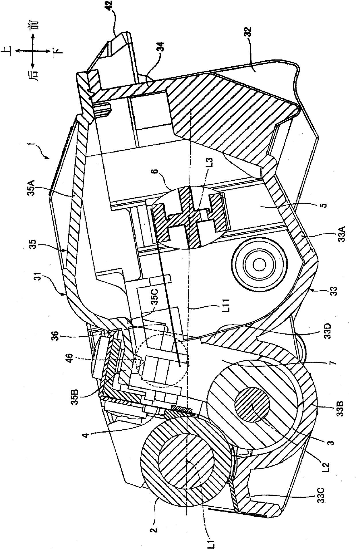
[0211] (1-1) Detailed structure of the developing cartridge according to the second embodiment
[0212] In the first embodiment, the developing cartridge 1 includes the toner storage chamber 5 and the developing chamber 7 in the developing frame 31 .
[0213] On the other hand, in the developing cartridge 1 according to the second embodiment, as Figure 8A , 8B As shown, the developing chamber 7 also serves as the toner containing chamber 5 in the developing frame 31 .
[0214] That is, in the second embodiment, the developing cartridge 1 does not include the agitator 6 . In addition, the front wall 34 is located on the front side of the developing coupling 71 in the front-rear direction.
[0215] In the developing cartridge 1 , the developing chamber 7 is defined by a front wall 34 , a pair of side walls 32 , a bottom wall 33 and an upper wall 35 .
[0216] In the toner filling operation, when toner is filled through the filling port 46, the developing chamber 7 is filled...
no. 3 approach
[0222] (2-1) Detailed structure of the developing cartridge according to the third embodiment
[0223] In the first embodiment, the filling port 46 overlaps the developing coupling 71 when projected in the left-right direction.
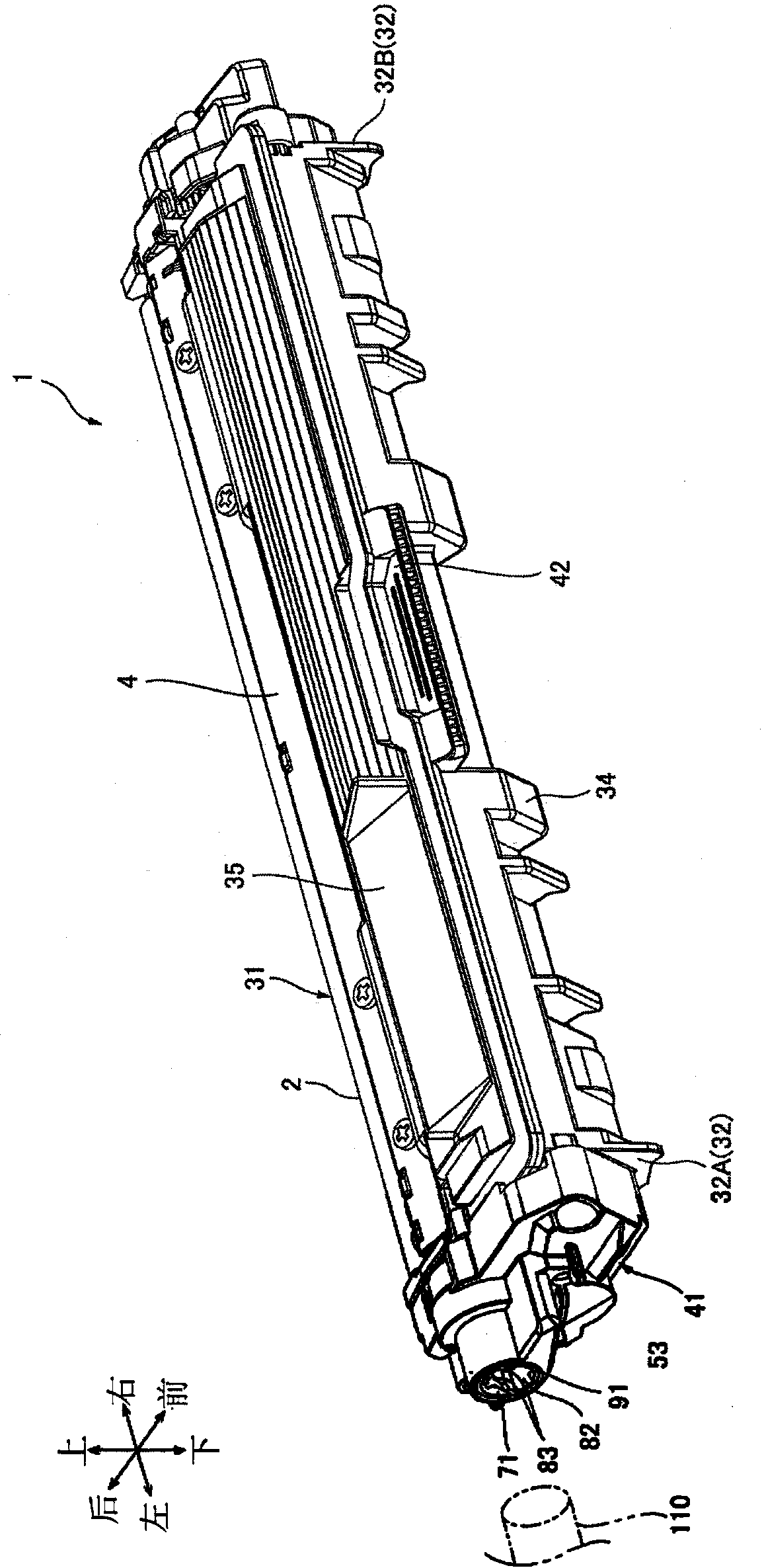
[0224] On the other hand, in the third embodiment, as Figure 10B As shown, a part of the filling port 100 is located outside the projected area of the developing coupling 71 when projected in the left-right direction.
[0225] That is, in the third embodiment, similarly to the second embodiment, the developing chamber 7 is also used as the toner containing chamber 5 in the developing frame 31 . In addition, if Figure 9 As shown, the developer cartridge 1 includes a fill port 100 instead of the fill port 46 .
[0226] Fill port 100 is located on the front wall of left side wall 32A. The filling port 100 has a substantially polygonal shape in a side view, and penetrates the left side wall 32A in the left-right direction.
[0227] The left side ...
PUM
 Abstract
Description
Claims
Application Information
 - R&D Engineer
- R&D Manager
- IP Professional
- Industry Leading Data Capabilities
- Powerful AI technology
- Patent DNA Extraction
Browse by: Latest US Patents, China's latest patents, Technical Efficacy Thesaurus, Application Domain, Technology Topic, Popular Technical Reports.
© 2024 PatSnap. All rights reserved.Legal|Privacy policy|Modern Slavery Act Transparency Statement|Sitemap|About US| Contact US: help@patsnap.com