
Washing and/or dewatering plants for cellulose pulp

一种纤维素纸浆、纸浆的技术,应用在纸浆脱水、纸浆打浆/精浆方法、纤维原料处理等方向,能够解决孔堵塞等问题,达到高能力、好洗涤的效果

Active Publication Date: 2017-09-12
VALMET OY
View PDF4 Cites 0 Cited by
  • Summary
  • Abstract
  • Description
  • Claims
  • Application Information

AI Technical Summary

Problems solved by technology

However, the pores have a tendency to clog

Method used


Image

  • Washing and/or dewatering plants for cellulose pulp
  • Washing and/or dewatering plants for cellulose pulp
  • Washing and/or dewatering plants for cellulose pulp

Examples


Embodiment Construction

[0016] In the drawings, similar or corresponding elements are marked with the same reference signs.

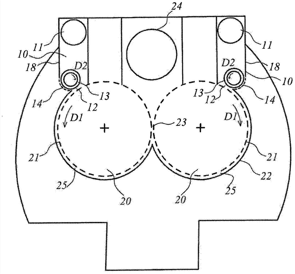
[0017] figure 1 A washing and / or dewatering device 100 for cellulose pulp is shown. The device 100 is in the form of a two-roll press 100 in this example. The device 100 includes two cylindrical press rolls 20 cooperating. The two press rolls 20 are arranged to rotate in opposite directions (as indicated by the arrows) during operation, and each have a first rotatable permeable surface 21, more specifically, a perforated metal plate or the like. The press roll 20 is partially circumferentially surrounded by grooves (also called grooves). The groove includes a groove wall 22 and a groove chamber 25 formed by a guide surface.

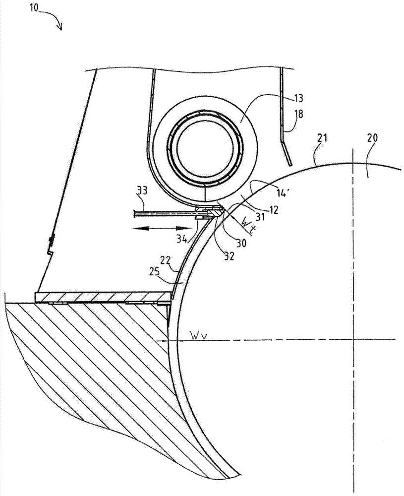
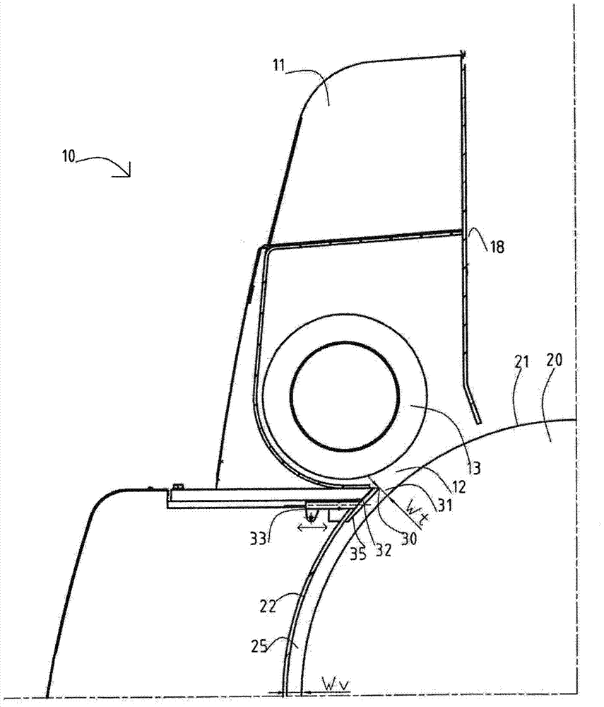
[0018] A pulp distribution device 10 is associated with each press roll 20. The pulp distribution device 10 is arranged at the upper part of the press roll 20 for distributing the pulp onto the perforated roll surface 21. The pulp distribution device 10 i...


PUM


Abstract

The invention relates to an apparatus (100) for washing and / or dewatering of cellulose pulp, the arrangement (100) comprising: a first movable permeable surface (21); a pulp delivery chamber wall (22) and a pulp delivery chamber (25), the pulp delivery chamber (25) has a chamber gap width (Wv) between the pulp delivery chamber wall (22) and the first movable permeable surface (21); and includes an inlet (11) and an outlet (12 ), the pulp distribution device (10) is arranged to distribute pulp through its outlet onto the first movable permeable surface (21). According to the invention, the pulp delivery chamber (25) is provided with a partial throttle (31) having a throttle gap width (Wt) close to the outlet (12) of the pulp distribution device (10), and wherein for initial dewatering The second permeable surface (14) is arranged before the partial restriction (31).

Description

Technical field [0001] The invention relates to a washing and / or dewatering equipment for cellulose pulp. Background technique [0002] Pulp washing is a key operation in the pulp production line. There are many different types of washing equipment available, some of which are based on press washing and include devices that press pulp to remove liquids. After pressing, the pulp can be diluted to the desired consistency if appropriate. [0003] For example, a well-known washing device is a two-roll press of the general type disclosed in US 3,980,518. It has two counter-rotating rollers with perforated outer surfaces. The pulp web is formed on the respective rolls and is transported in the direction of rotation in a groove partially surrounding the rolls to the so-called nip between the rolls. The liquid removed from the pulp, the filtrate, passes through the surface of the perforated roll in the radially inward direction and is led to the end of the press roll, from which it is ...

Claims


Application Information

Patent Timeline
Patent Type & Authority Patents(China)
IPC IPC(8): D21C9/18D21C9/06B01D33/72D21D1/40D21F1/02D21F1/04
CPCD21C9/06D21C9/18D21D1/40D21F1/74B01D33/72D21F1/02D21F1/04D21F1/66
Inventor T·洛夫P·彼得森J·奥加德H·洛夫格兰P·沃林P·尼克韦斯特J·麦格纽森
Owner VALMET OY
Learn More