
A dynamic adjustment method, system and electronic equipment for load current

A load current and dynamic adjustment technology, applied in the electronic field, can solve the problems of large design margin, design margin cannot be maximized, and cannot be satisfied at the same time, so as to achieve the effect of giving full play to the design ability

Active Publication Date: 2017-09-29
湖州帷幄知识产权运营有限公司
View PDF5 Cites 0 Cited by
  • Summary
  • Abstract
  • Description
  • Claims
  • Application Information

AI Technical Summary

Problems solved by technology

[0008] In view of the shortcomings of the prior art described above, the purpose of the present invention is to provide a dynamic adjustment method, system and electronic equipment for load current, which are used to solve the excessive and insufficient design margins seen in the prior art It will not be able to maximize the design capabilities of the chip, and it will not be able to meet the problem of running devices with different load currents on the same power supply or charging device at the same time.

Method used


Image

  • A dynamic adjustment method, system and electronic equipment for load current
  • A dynamic adjustment method, system and electronic equipment for load current
  • A dynamic adjustment method, system and electronic equipment for load current

Examples


Embodiment 1

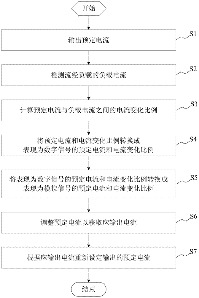
[0043] This embodiment provides a method for dynamically adjusting load current, and the method for dynamically adjusting load current includes the following steps:

[0044] Output predetermined current;

[0045] Detect the load current flowing through the load;

[0046] Calculating the current change ratio between the predetermined current and the load current;

[0047] Dynamically adjusting the predetermined current according to the current change ratio to obtain the output current;

[0048] The predetermined current is reset according to the output current.

[0049] The dynamic adjustment method of the load current described in this embodiment will be described in detail below in conjunction with the diagram. See image 3 , Is shown as a schematic flow diagram of a method for dynamically adjusting the load current in an embodiment. Such as image 3 As shown, the method for dynamically adjusting the load current specifically includes the following steps:

[0050] S1, output a predeter...

Embodiment 2

[0059] This embodiment provides a dynamic adjustment system for load current, wherein the dynamic adjustment system for load current includes:

[0060] A predetermined current output module for outputting a predetermined current;

[0061] A detection module, connected to the predetermined current output module and the load, and used to detect the load current flowing through the load;

[0062] A calculation module, connected to the predetermined current output module and the detection module, and used to calculate the current change ratio between the predetermined current and the load current;

[0063] The control module is connected to the predetermined current output module and the calculation module, and is configured to dynamically adjust the predetermined current according to the current change ratio to obtain the output current, and make the predetermined current output module reset according to the output current Set a predetermined current.

[0064] The dynamic adjustment syste...


PUM


Abstract

The invention provides a dynamic adjustment method for load current. The method comprises the following steps of outputting preset current, detecting the load current flowing through a load, calculating the current change ratio of the preset current to the load current, dynamically adjusting the preset current according to the current change ratio so as to obtain the current which should be output, and setting the preset current again according to the current which should be output. According to the dynamic adjustment method for the load current, overcurrent protection of different loads for using the same charging equipment can be achieved, and the design capacity of a chip can be brought into play to the maximum extent.

Description

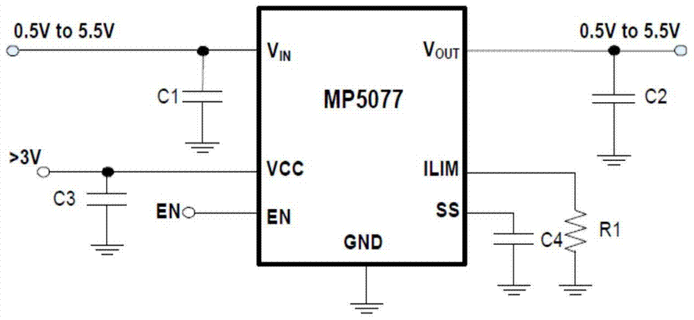
Technical field [0001] The present invention belongs to the field of electronic technology, and relates to an adjustment method and system, in particular to a dynamic adjustment method, system and electronic equipment of a load current. Background technique [0002] Now more and more electronic products are equipped with USB charging and power supply ports, such as wireless routers, EPON, GPON, set-top boxes, televisions and other electronic products. For users, powered devices with USB interfaces such as mobile phones, PADs, USB flash drives, hard drives, digital cameras, etc., these electronic devices with different functions have different charging and working power consumption, some are less than 1A, some Is as large as several amperes. How do we ensure that different loads are using the same charging equipment for overcurrent protection? [0003] See figure 1 , Shown as a schematic diagram of a circuit with a fixed load current limit in the prior art. figure 1 C1 is the filt...

Claims


Application Information

Patent Timeline
Patent Type & Authority Patents(China)
IPC IPC(8): G05F1/573
CPCG05F1/5735
Inventor 邓张雷
Owner 湖州帷幄知识产权运营有限公司
Learn More