
Sample detection to initiate timing of an electrochemical assay

a technology of electrochemical assay and sample detection, which is applied in the direction of liquid/fluent solid measurement, biomass after-treatment, enzymology, etc., can solve the problems of affecting the timing of the electrochemical assay, affecting the detection accuracy of samples, etc., and the initial current generally decreases with the decrease of the analyte concentration

Inactive Publication Date: 2001-02-27
LIFESCAN IP HLDG LLC
View PDF7 Cites 788 Cited by
  • Summary
  • Abstract
  • Description
  • Claims
  • Application Information

AI Technical Summary

Benefits of technology

The present invention provides a method and apparatus for measuring analyte concentration electrochemically, which includes defining with great accuracy the time at which a sample that is applied to the reaction zone of an electrochemical diagnostic strip bridges the gap between the electrodes. Determining the sample application time (more precisely, the sample detection time; we use the terms interchangeably) accurately permits greater accuracy and precision of the assay done on the sample.

Problems solved by technology

Since diabetes can cause dangerous anomalies in blood chemistry, it can contribute to vision loss, kidney failure, and other serious medical consequences.
This could lead to an inaccurate measurement, especially at low analyte concentrations.
The prior art method of applying a constant potential to detect sample application has another disadvantage in that the initial current generally decreases with decreasing analyte concentration.
Thus it is more difficult to determine an initial sample detection time for low-analyte samples.
To further complicate matters, the presence of a high concentration of red blood cells also decreases the initial current.

Method used


Image

  • Sample detection to initiate timing of an electrochemical assay
  • Sample detection to initiate timing of an electrochemical assay
  • Sample detection to initiate timing of an electrochemical assay

Examples


Embodiment Construction

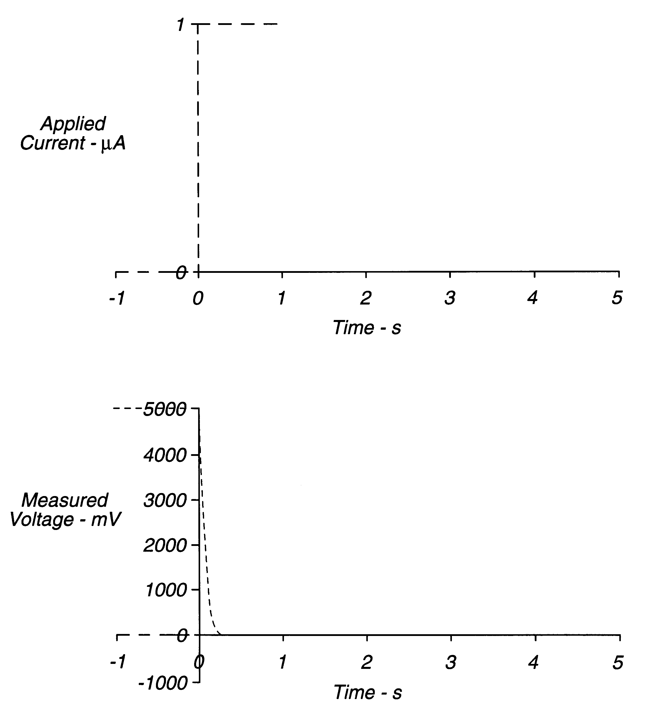
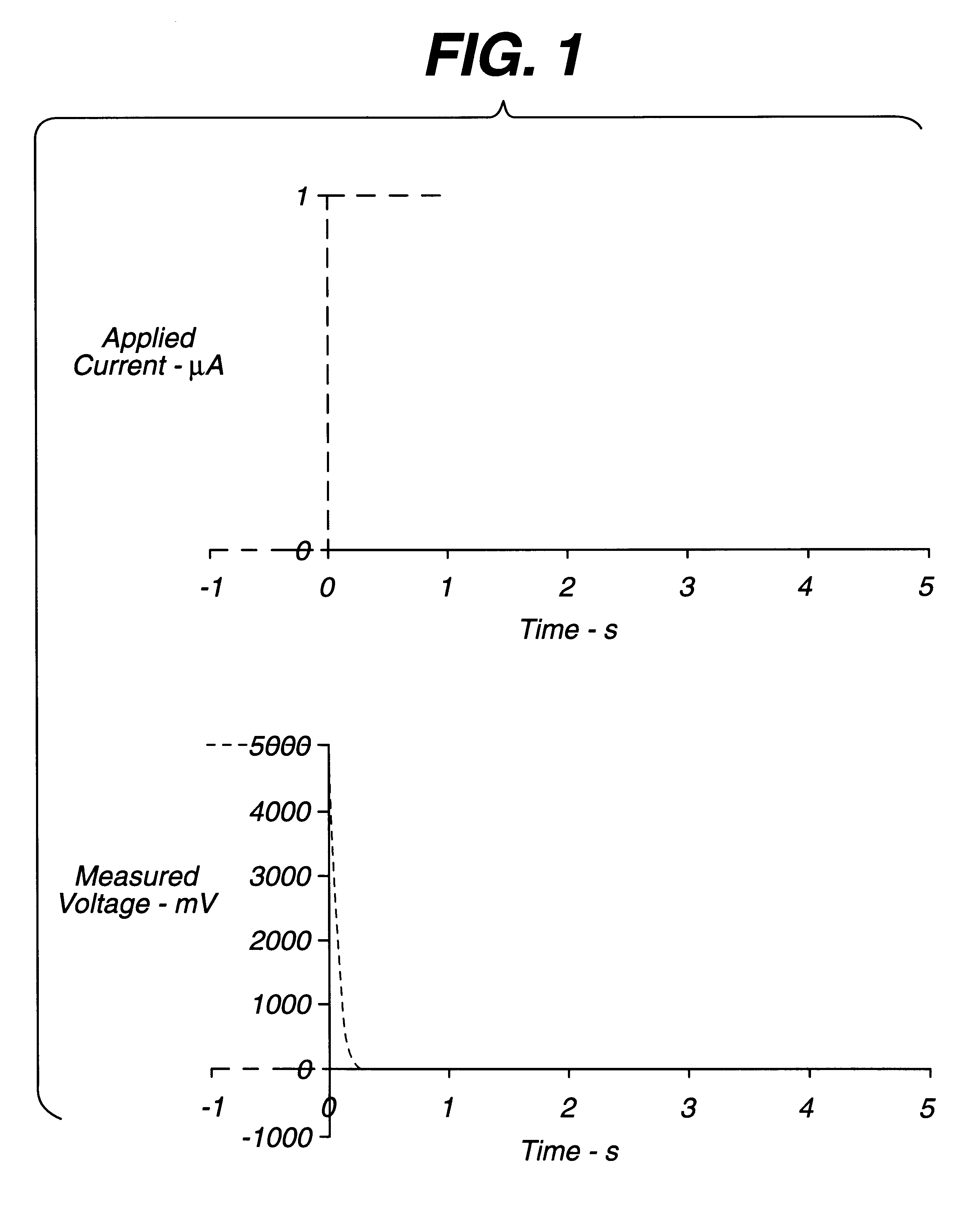
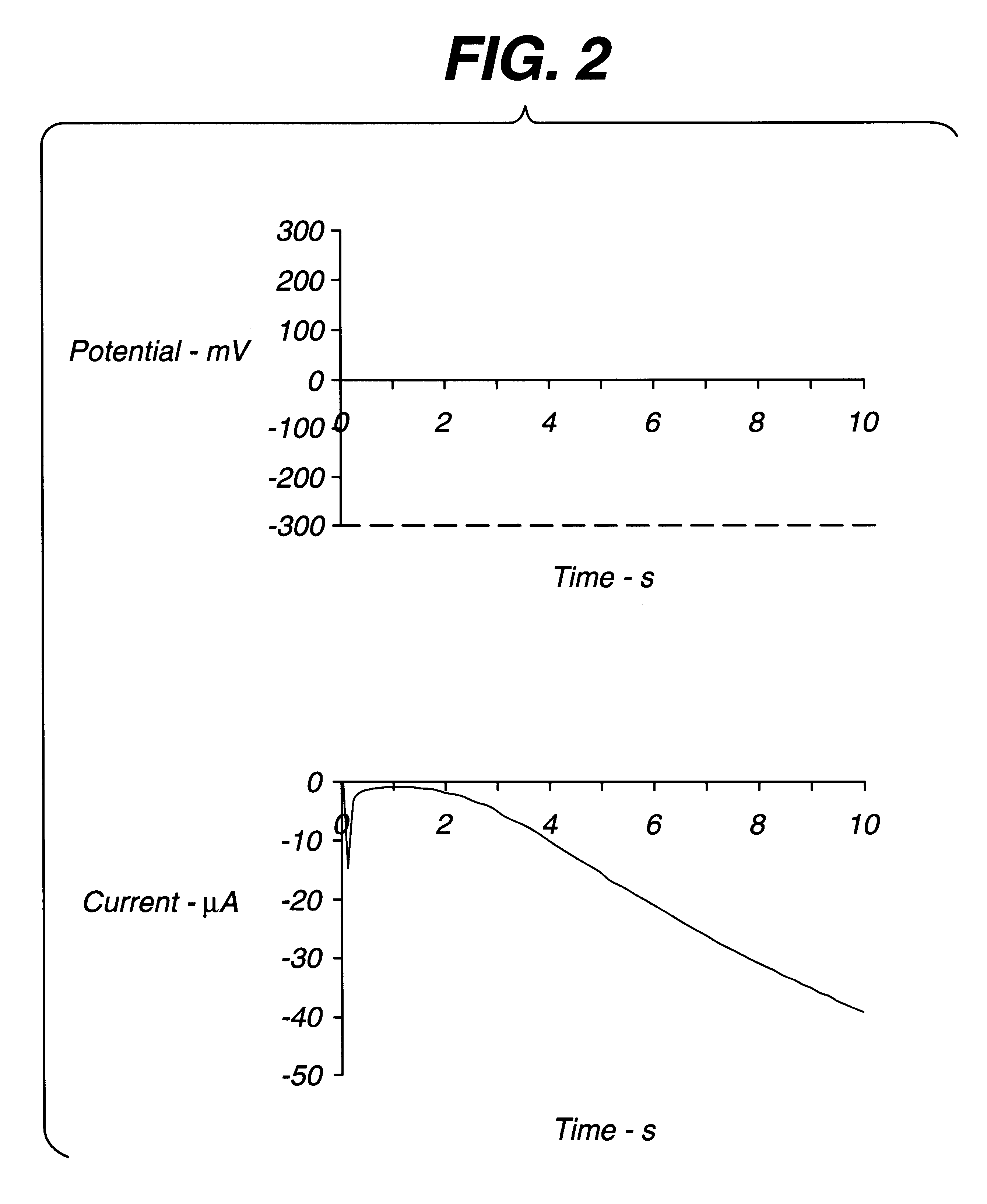
The circuit of FIG. 6 was established, with strip S being a thin layer electrochemical glucose strip of the type shown in FIG. 5, having Pd and Au electrodes. The Pd electrode was coated with a layer of buffer, glucose dehydrogenase (PQQ), and ferricyanide. A constant, small (.about.1 .mu.A) non-perturbing current was applied between the working electrode and counter / reference electrode of the dry glucose strip. Because the strip was dry, the resistance between the working and counter / reference electrode was essentially infinite. After a whole-blood sample was applied across the cell, a drop in voltage was observed. A threshold of about 50 to 500 mV initiated the start time (a threshold of about 300 mV is preferred). After sample was detected, the instrument switched from applying a constant current to applying a constant voltage. Measurement of the current through the sample as a function of time permitted the glucose concentration to be calculated.

It will be understood by those sk...


PUM

PropertyMeasurementUnit
Timeaaaaaaaaaa
Concentrationaaaaaaaaaa
Currentaaaaaaaaaa

Abstract

An electrochemical assay includes a method for determining with great accuracy the time at which an applied sample bridges a gap between the electrodes of an electrochemical cell. The method involves applying a constant small current across the gap, while monitoring the potential difference between the electrodes. The time at which the sample bridges the gap is marked by a sharp drop in the potential. A constant voltage is applied after the sample is detected, and the current and / or charge through the sample is monitored over a period of time. From the measured current or charge, the analyte concentration of interest can be calculated.

Description

1. Field of the InventionThis invention relates to an electrochemical device for measuring the concentration of an analyte in a biological fluid; more particularly, to a mechanism for determining the time at which the fluid provides an electrical connection between working and reference electrodes of the device.2. Description of the Related ArtA variety of medical diagnostic procedures involve tests on biological fluids, such as blood, urine, or saliva, to determine an analyte concentration in the fluid. Among the analytes of greatest interest is glucose, and dry phase reagent strips incorporating enzyme-based compositions are used extensively in clinical laboratories, physicians, offices, hospitals, and homes to test samples of biological fluids for glucose concentration. In fact, reagent strips have become an everyday necessity for many of the nation's estimated 16 million people with diabetes. Since diabetes can cause dangerous anomalies in blood chemistry, it can contribute to v...

Claims


Application Information

Patent Timeline
IPC IPC(8): G01N27/416G01N33/487C12M1/40G01N33/483C12Q1/00C12Q1/32C12Q1/54G01N27/26G01N27/327
CPCG01N27/3273G01N27/26
Inventor OHARA, TIMOTHY J.TEODORCZYK, MARIAKERMANI, MAHYAR Z.
Owner LIFESCAN IP HLDG LLC
Learn More