
Sensor, a sensor system, and a method of sensing in a floatation tank

a floatation tank and sensor technology, applied in the field of sensors, can solve the problems of inability to measure accurately, inability to detect the movement of the sensor, etc., and achieve the effect of greater accuracy and/or precision of measuremen

Active Publication Date: 2021-11-16
BINMARTINE
View PDF19 Cites 0 Cited by
  • Summary
  • Abstract
  • Description
  • Claims
  • Application Information

AI Technical Summary

Benefits of technology

The patent describes a system for measuring properties of substances in a flotation tank. The system includes an array of transducers placed in the tank, which can transmit signals to each other. The transducers can be positioned in different layers of the tank, and the system can be tilted at different angles to accurately measure the height of different substances. The system can provide useful information to operators of the flotation tank, allowing them to determine the status of the tank and make adjustments to improve its performance.

Problems solved by technology

This measurement has presented various problems, such as:The slurry / pulp level is positioned below a heavy froth layer;The froth layer contains recovered metal in suspension which builds up on any intrusive objects, including instruments for measuring;The slurry / pulp liquid also contains material that can adhere to anything intrusive, which may include scaling and other types of build-up;The density of the slurry / pulp and the froth changes as the ore body being processed changes;The dielectric of the slurry / pulp is subject to change, which results in great difficulty in using electrical properties if consistent measurement of the slurry / pulp is desired.
It has been desired to obtain a sufficiently accurate level measurement of the slurry / pulp, because if the slurry / pulp overflows the launders of the flotation cell / flotation tank, contamination of the froth concentrate in the concentrate thickener will require expensive remediation costs, which may include further processing of the concentrate.
If the froth density becomes too high, the froth will collapse back on itself, resulting in a failure of the process.
However, employing a human operator is expensive, and can be prone to human error.
Further, a camera can only detect that froth is not overflowing the launder, but it cannot predict the eventual collapse of the froth due to density increase.
The flotation cell / flotation tank may only work efficiently when there is froth recovery over the launder.
Previously, in order to determine some of the desired information / parameters / operating conditions of mining processes, there have been various techniques and instruments used, all of which have problems.
Further, mechanical wear for a displacement float is a problem and occurs at a high rate, as the flotation cell / flotation tank is aerated and agitated.
Another problem with displacement floats is that they sometimes stick in position.
These problems cause high maintenance costs and high operation costs, with failures of the displacement float leading to costly errors and / or shutdowns of the mining processing.
However, many, if not all of the same problems are found to occur with this particular alternative.
However, this technology is affected by density change in the slurry / pulp.
Accordingly, a pressure transmitter produces a low level of accuracy.
Furthermore, the pipes of the pressure transmitter are prone to blocking up, which requires constant purging.
In this regard, the pressure transmitter technology does not provide sufficiently reliable information and it requires constant maintenance, which leads to further expense and loss of productivity in the mining processes.
A greater weakness of conductivity probes is the build-up on those probes during the normal processes of operating a tank flotation cell / flotation tank.
However, such conductivity probes also have problems if build-up is excessive and also if the build-up is left to dry on the probe.
Such unreliability is unacceptable for expensive mining processes.
A lack of automation and employing expensive, fallible human operators is leading to costly and unreliable mining processing.

Method used


Image

  • Sensor, a sensor system, and a method of sensing in a floatation tank
  • Sensor, a sensor system, and a method of sensing in a floatation tank
  • Sensor, a sensor system, and a method of sensing in a floatation tank

Examples


Embodiment Construction

[0022]In an embodiment, the controller is further adapted to control each transducer to be selectively in a cleaning mode for generating a signal which forms cavitation in one or more of the at least one substance, such that, if one or more of the substances has accumulated on and / or near the transducer, the cavitation removes at least some of the accumulation from on and / or near the transducer. In this regard, the pulse amplitude of the signal is great enough to cause a phenomenon called “rarefaction”, which in turn causes cavitation. The cavitation may result in a substance dissolving, if it is a substance soluble in the medium of the flotation tank (usually water), and if the cavitation energy is sufficient to effect such dissolving. The cavitation may result in a substance being displaced, if it is not soluble in the medium, for example: oils, grease and scale.

[0023]It will be understood that the controller being adapted for a given task encompasses the controller being programm...


PUM


Abstract

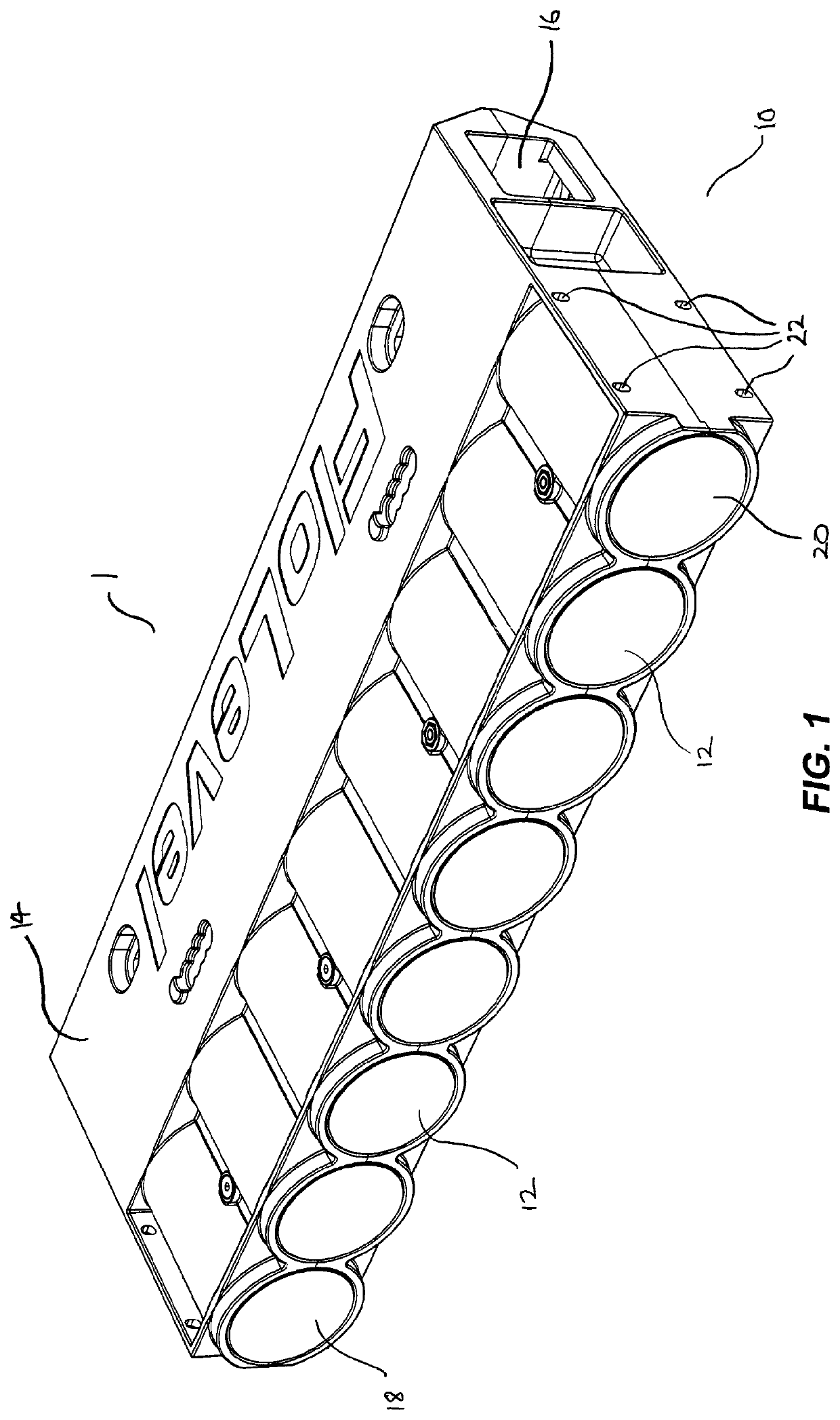
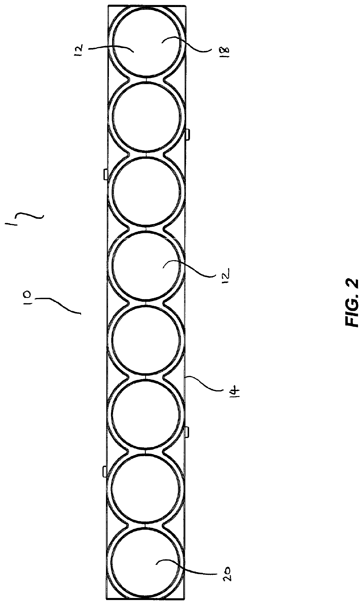
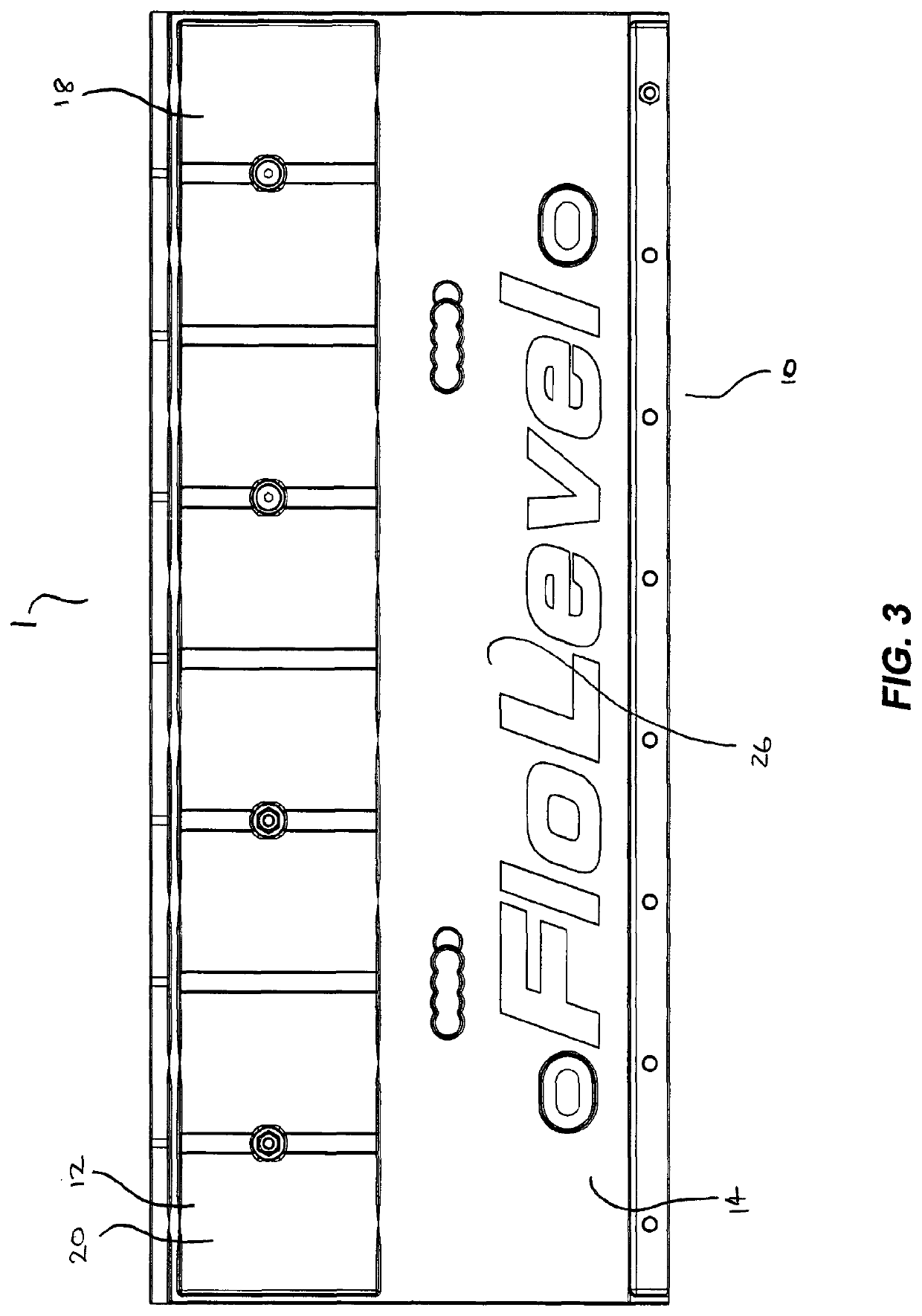
A sensor (1) including at least one array (10), including a plurality of acoustic transducers (12); a controller (42) for controlling each transducer (12) to be selectively in a generation mode for generating an analysis signal, or a reception mode for receiving an analysis signal, and, for controlling the sensor (1) to perform scans of the at least one array (10), each scan having a plurality of scan steps, such that, during each scan step, at least one transducer (12) is in the generation mode and at least one other transducer (12) is in the reception mode; and, a processor (44) for processing one or more signals receivable from one or more of the controller (42), a transducer (12) in generation mode and a transducer (12) in reception mode to determine at least one characteristic from the one or more signals.

Description

FIELD OF THE INVENTION[0001]The present invention relates to a sensor, a sensor system and / or a method of sensing, which may be useful for mining applications. Further, the invention may be particularly useful where it is desired to ascertain levels of various substances in a flotation cell / flotation tank.BACKGROUND OF THE INVENTION[0002]In the mining industry, it has been desired to be able to measure the level of substances in, for example, a flotation cell or flotation tank. This measurement has presented various problems, such as:[0003]The slurry / pulp level is positioned below a heavy froth layer;[0004]The froth layer contains recovered metal in suspension which builds up on any intrusive objects, including instruments for measuring;[0005]The slurry / pulp liquid also contains material that can adhere to anything intrusive, which may include scaling and other types of build-up;[0006]The density of the slurry / pulp and the froth changes as the ore body being processed changes;[0007]...

Claims


Application Information

Patent Timeline
Patent Type & Authority Patents(United States)
IPC IPC(8): G01F23/296B03D1/02
CPCG01F23/296B03D1/028G01F23/2961G01F23/2965G01F23/2968
Inventor STIRLING, ROBERT SIDNEYVIVAKANANTHAM, RAVI
Owner BINMARTINE
Learn More