DC switch of motor

A DC switch and electronic commutation technology, applied in the direction of electric switches, circuits, electrical components, etc., can solve the problems of complex assembly process, low assembly efficiency, and low reliability, and achieve a solid structure, simple assembly, and stable and reliable performance. Effect

Inactive Publication Date: 2016-03-09
SUZHOU HUAZHIJIE TELECOM
View PDF5 Cites 2 Cited by
  • Summary
  • Abstract
  • Description
  • Claims
  • Application Information

AI Technical Summary

Problems solved by technology

[0002] In the switch industry of motors, the switches of electric drills and angle grinders are always pressed to turn on and released to turn off, while the current DC switch includes a base and a cover plate fixed to each other, and the cover plate is equipped with a circuit A moving contact assembly and a static contact assembly that cooperate with each other are installed on the base, and a push rod is installed on the base. One end of the push rod runs through the base and is exposed, and a return spring is arranged between the other end and the base. The push rod drives the action of the moving contact assembly to connect or disconnect the static contact assembly. The push rod is equipped with a resistance adjusting shrapnel, and

Method used


Image

  • DC switch of motor
  • DC switch of motor
  • DC switch of motor

Examples


Embodiment Construction

[0033] The present invention will be described in further detail below through specific examples.

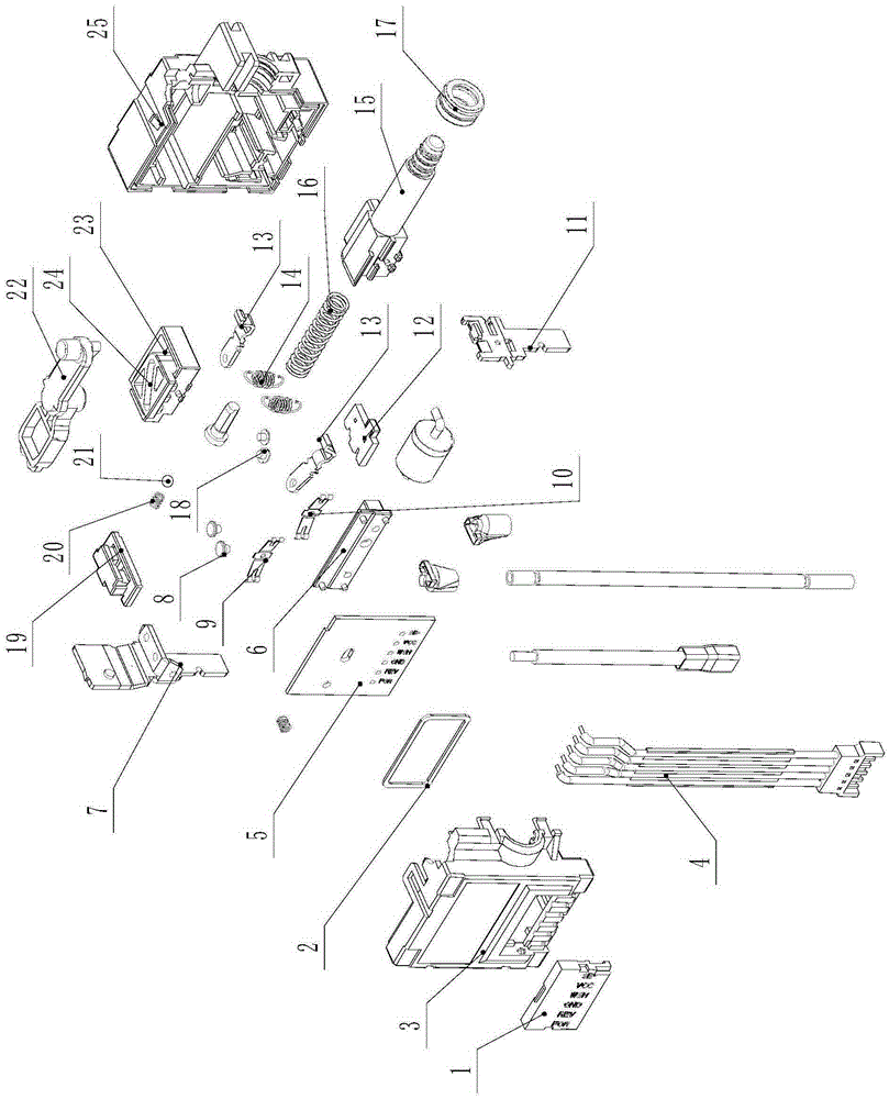
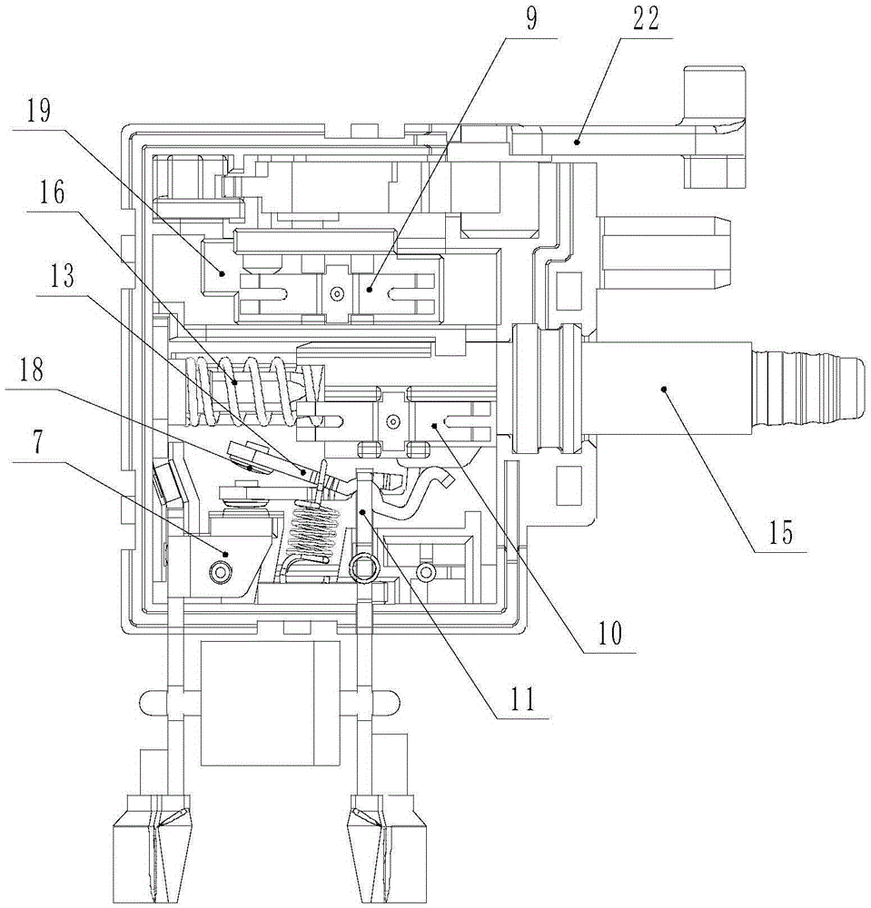
[0034] Such as Figure 1 to Figure 13 As shown, a motor DC switch includes a base 25 and a cover plate fixed to each other, and the base 25 and the cover plate are clamped and fixed around the base 25 and the cover plate through a snap-fit ​​structure.

[0035] Such as figure 1 , Figure 10 , Figure 11 and Figure 12As shown, the cover plate includes a cover plate body 3 and a gland 1, the cover plate body 3 is provided with several half grooves 301 for wiring, and the side of the gland plate 1 close to the cover plate body 3 is provided with Several crimping half-grooves 101, the crimping half-grooves 101 and cable-arranging half-grooves 301 are in one-to-one correspondence, each of the cable-arranging half-grooves 301 and crimping half-grooves 101 is provided with dust-proof flanges 302, 102 , used to compress the wiring harness 4, the other side of the cover body 3 is m...


PUM


Abstract

The invention discloses a DC switch of a motor. The DC switch comprises a pedestal and a cover plate, a circuit board is mounted on the cover plate, a moving contact assembly and a static contact assembly cooperated with the moving contact assembly are mounted on the pedestal, a push rod is mounted on the pedestal, the push rod drives the moving contact assembly to move so that the moving contact assembly is connected with or disconnected from the static contact assembly, a resistance adjusting spring is mounted on the push rod, a resistance adjusting connecting finger is arranged on the circuit board, an electronic commutation mechanism is arranged on the pedestal and comprises a slide block, the slide block is mounted on the pedestal in a sliding manner, a commutation spring is fixed to the slide block, the circuit board is provided with a commutation connecting finger which makes contact with the commutating spring, a commutation handle is rotationally mounted on the pedestal, a driving slide block is in transmission connection between the commutation handle and the slide block and slides in a repeated manner, and a locating mechanism which locates the commutation handle is arranged on the pedestal. According to the DC switch, the electronic commutation mechanism is simple in structure, operation is reliable, commutation is rapid and accurate and assembling is simple.

Description

technical field [0001] The invention relates to a DC switch, in particular to a motor DC switch. Background technique [0002] In the switch industry of motors, the switches of electric drills and angle grinders are always pressed to turn on and released to turn off, while the current DC switch includes a base and a cover plate fixed to each other, and the cover plate is equipped with a circuit A moving contact assembly and a static contact assembly that cooperate with each other are installed on the base, and a push rod is installed on the base. One end of the push rod runs through the base and is exposed, and a return spring is arranged between the other end and the base. The push rod drives the action of the moving contact assembly to connect or disconnect the static contact assembly. The push rod is equipped with a resistance adjusting shrapnel, and the corresponding position on the circuit board is provided with a resistance adjusting metal that slides and fits with the...

Claims


Application Information

Patent Timeline
IPC IPC(8): H01H3/32H01H9/02
CPCH01H3/32H01H9/02
Inventor 苏康
Owner SUZHOU HUAZHIJIE TELECOM
Why Eureka
Try Eureka