Reciprocating supercharger capable of stably reversing

A reciprocating, supercharger technology, applied in the direction of fluid pressure converters, mechanical equipment, etc., can solve the problems of affecting the reversing speed, poor output pressure stability, small flow rate of the electromagnetic reversing valve, etc., to reduce manufacturing costs and failures speed, reducing shock, increasing stability and speed of commutation

Pending Publication Date: 2020-03-10
郑州浩普液压设备有限公司
View PDF2 Cites 0 Cited by
  • Summary
  • Abstract
  • Description
  • Claims
  • Application Information

AI Technical Summary

Problems solved by technology

Existing reciprocating superchargers are mostly matched with electromagnetic reversing valves for reversing, but the electromagnetic reversing valve has a small flow rate and low reversing frequency, resulting in poor stability of the output pressure, and can only perform small flow and low pressure boosting
The ultra-high pressure supercharger disclosed in Chinese patent ZL201520640556.7 and the reciprocating supercharger disclosed in ZL201720584115.9 both realize hydraulic control reversing, which can ensure a large flow rate while super-high pressure supercharging , but the commutation structure is relatively complex, and the cost disadvantage is prominent when matching some relatively small equipment, and the complex structure brings more leakage points and higher failure rate
[0003] When the piston of the reciprocating supercharger travels to the limit position on one side, due to the sharp decrease in the space of the piston chamber on one side and the blockage of the oil port, the movement of the piston will be hysteresis, which will affect the reversing speed and seriously affect the stability of the pressure.

Method used


Image

  • Reciprocating supercharger capable of stably reversing
  • Reciprocating supercharger capable of stably reversing

Examples


Embodiment Construction

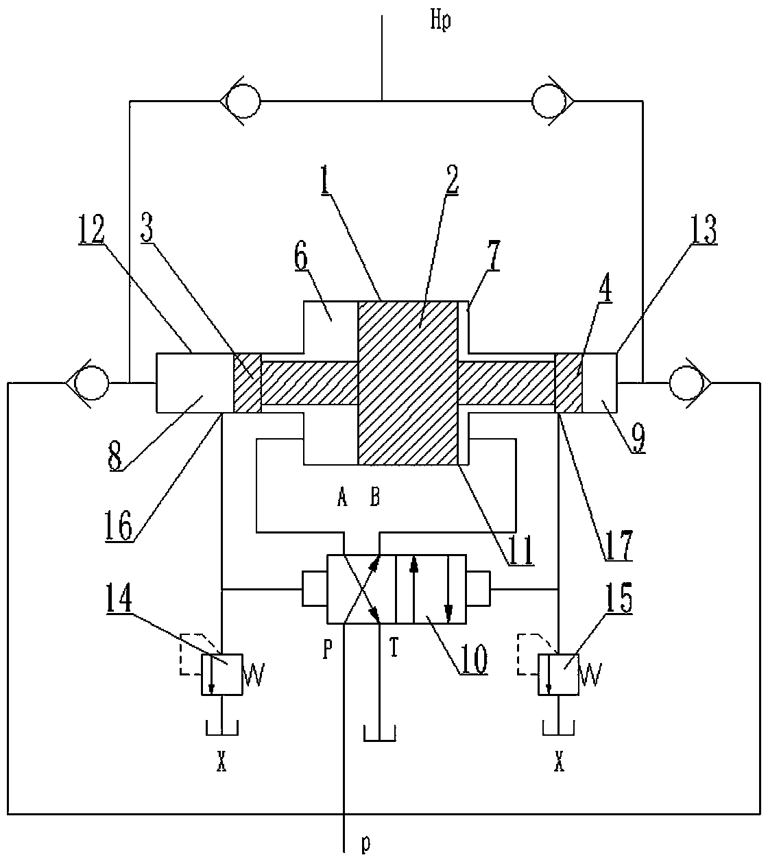
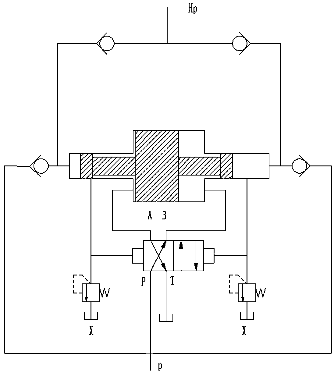
[0012] Such as figure 1 As shown, a hydraulically controlled reciprocating booster includes a reciprocating booster cylinder, an electromagnetic reversing valve 10, a left overflow valve 14, and a right overflow valve 15. The reciprocating booster cylinder includes a cylinder body 1, which is composed of a piston cylinder 11 in the middle and a left booster cylinder 12 and a right booster cylinder 13 at both ends. The piston 2 is arranged in the piston cylinder 11, and the left piston rod 3 is arranged in the left In the boost chamber, the right piston rod 4 is arranged in the right boost cylinder 13, the outer diameters of the left and right piston rod ends match the inner diameters of the left and right boost cylinders, and the outer diameter from the end to the piston is smaller than the outer diameter of the ends. The left piston cavity 6 is formed between the piston 2, the piston cylinder 11, the left booster cylinder 12, and the ends of the left piston rod 3, and the rig...


PUM


Abstract

The invention relates to a hydraulic supercharger, in particular to a reciprocating supercharger capable of stably reversing. The reciprocating supercharger comprises a reciprocating supercharging cylinder and a matched hydraulic control reversing valve, wherein the supercharging cylinder comprises a cylinder body, a piston arranged inside the cylinder body, a left piston rod and a right piston rod at the two ends of the piston, the cylinder body comprises a middle piston cylinder, a left supercharging cylinder and a right supercharging cylinder at the two ends, and a left piston cavity and aright piston cavity are formed between the piston and the cylinder body; a left supercharging cavity is formed between the left piston rod and the cylinder body, a right supercharging cavity is formedbetween the right piston rod and the cylinder body, the outer diameters of the end parts of the left piston rod and the right piston rod are matched with the inner diameters of the left superchargingcylinder and the right supercharging cylinder, and the outer diameters of the end parts to the piston parts are smaller than the outer diameters of the end parts. By improving the piston rod structure, the left piston cavity and the right piston cavity are expanded into the supercharging cylinder, and when the piston is in the limit position, the piston cavities always keep sufficient margin, sothat the impact is effectively reduced, and the supercharging stability and the reversing speed are greatly increased.

Description

technical field [0001] The invention relates to a hydraulic booster, in particular to a reciprocating booster capable of stably reversing. Background technique [0002] The hydraulic boosters currently used in the market are mainly traditional single-cylinder boosters and bi-directional reciprocating boosters. The existing reciprocating superchargers are mostly matched with electromagnetic reversing valves for reversing, but the electromagnetic reversing valve has a small flow rate and low reversing frequency, resulting in poor stability of the output pressure, and can only perform small flow and low pressure boosting. The ultra-high pressure supercharger disclosed in Chinese patent ZL201520640556.7 and the reciprocating supercharger disclosed in ZL201720584115.9 both realize hydraulic control reversing, which can ensure a large flow rate while super-high pressure supercharging , but the commutation structure is relatively complex, and the cost disadvantage is prominent whe...

Claims


Application Information

Patent Timeline
Patent Type & Authority Applications(China)
IPC IPC(8): F15B3/00
CPCF15B3/00
Inventor 佘喜旺康代扣王铁锁昝际伟昝际姣李瑞军
Owner 郑州浩普液压设备有限公司
Why Eureka
Try Eureka