Drainage With Multistage Syphon Odor Seal

A technology of drainage device and siphon, which is applied to water supply devices, indoor sanitary pipeline devices, drainage structures, etc., and can solve problems such as boundary condition restrictions

Active Publication Date: 2016-03-16
GEBERIT INT AG
View PDF5 Cites 2 Cited by
  • Summary
  • Abstract
  • Description
  • Claims
  • Application Information

AI Technical Summary

Problems solved by technology

In some cases even boundary conditions that are no longer changeable in the planning create constraints, especially in the renovation of old buildings

Method used


Image

  • Drainage With Multistage Syphon Odor Seal
  • Drainage With Multistage Syphon Odor Seal
  • Drainage With Multistage Syphon Odor Seal

Examples


Embodiment Construction

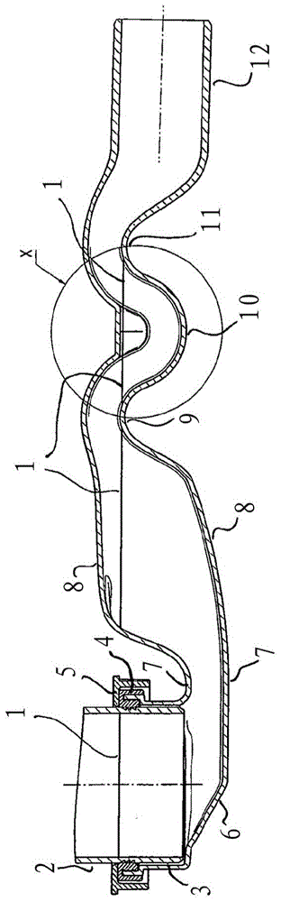
[0031] exist figure 1 A drainage device according to the invention is shown as an exemplary embodiment in longitudinal section. Here, the main flow direction of the water is from left to right and the view corresponds to the nominal installation position, wherein the nominal water level provided with reference numeral 1 is plotted. On the left side there can be seen a pipe connection 2 which, for example, can be connected on the underside to a conventional shower drain and allows waste water to flow down from the drain formed by the gutter when the shower is in progress. The pipe connection 2 is inserted into the widened end of the drain cup-shaped cylindrical part 3 of the drain and is sealed and held via a seal 4 and a collar-shaped safety ring 5 . The structures described so far are rotationally symmetric and known per se.

[0032] The cylindrical part 3 of the drain cup extends downwards in a no longer rotationally symmetrical section 6 of the drain cup, which has a beve...


PUM


Abstract

The invention provides a drainage. The drainage comprises the following components: an inlet side drain pot (3.6); a drain line (12) connected to the drain pot and a multistage syphon odor seal (3, 6-11), wherein the multistage syphon odor seal is provided with an internal air area; the drainage is characterized in that an air passage (13,14) is provided between the internal air area and a peripheral air field in the drainage on an inlet side and/or outlet side of the drainage.

Description

technical field [0001] The invention relates to a drainage device, for example for sanitary areas, such as floor drains for showers. Background technique [0002] Such drainage devices, in particular floor drains for showers, have been known per se for a long time. In addition to their main function of draining water from surfaces such as shower trays or floors and distributing it into the waste water network, drainage devices in most cases have the task of deodorizing. It is conceivable that unpleasant odors can escape from the waste water network, which can be blocked by so-called siphons, ie drain bends in correspondingly curved line guides. The anti-odor function requires a certain safety margin for the expected evaporation from the siphon and pressure fluctuations in the pipe network. The gas is forced through the siphon into the space in which the drain is installed. There are therefore different regulations and standards, such as EN1253, which maintain the odor bar...

Claims


Application Information

Patent Timeline
Patent Type & Authority Applications(China)
IPC IPC(8): E03C1/122E03C1/284E03F5/04
CPCE03C1/284E03C1/294E03F5/0407
Inventor 孙懿
Owner GEBERIT INT AG
Why Eureka
Try Eureka