
Internet household appliance control system

A home appliance control and control system technology, applied in the field of electronic information, can solve the problems that consumers cannot operate it, cannot meet the needs of consumers' menu functions, and cannot complete remote upgrades of small home appliance firmware, etc.

Inactive Publication Date: 2016-03-16
SHANGHAI CHUNMI ELECTRONICS TECH CO LTD +1
View PDF6 Cites 4 Cited by
  • Summary
  • Abstract
  • Description
  • Claims
  • Application Information

AI Technical Summary

Problems solved by technology

[0002] At present, traditional mechanically operated small household appliances (such as rice cookers, microwave ovens, etc.) are increasingly unable to meet the needs of modern fast-paced life due to defects such as few functions and lack of appointment timing functions.
[0003] Although small household appliances controlled by computer chip programs can monitor the temperature in real time to flexibly adjust the firepower, they still have the following disadvantages: 1. Although some menus have been added compared to traditional mechanical cookers, the menus are fixed and cannot be changed, which cannot satisfy consumption The user's demand for more menu functions
2. The control of firepower and temperature is realized automatically, and consumers cannot operate it
3. Smartphones and wireless networks have penetrated into households. Currently, the small household appliances used by people cannot satisfy consumers’ control of household appliances through smartphones, and they can enjoy delicious food while entertaining.
4. Unable to complete the remote upgrade of the firmware of small appliances

Method used


Image

  • Internet household appliance control system
  • Internet household appliance control system

Examples


Embodiment Construction

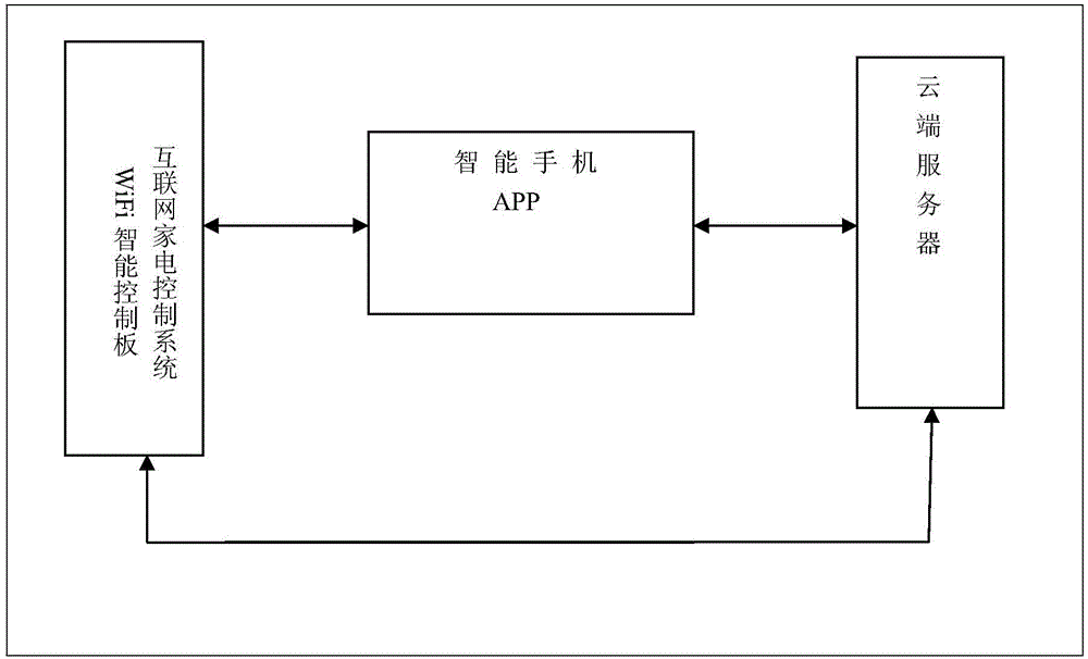
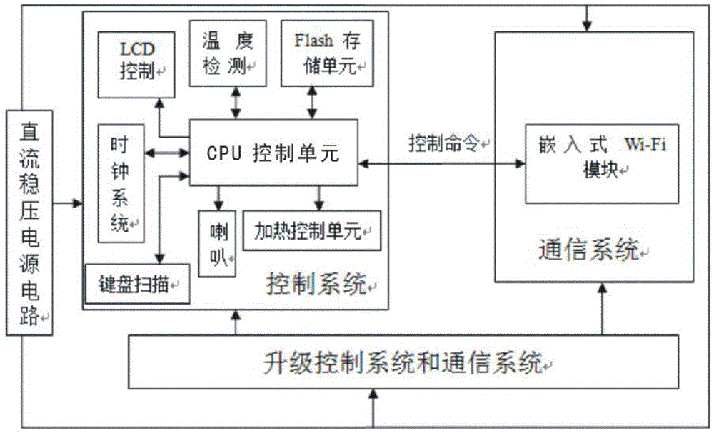
[0017] Such as figure 1 Shown: An Internet home appliance control system used in rice cookers. The system consists of a smart phone, a WIFI smart control board and a cloud server. The smart phone communicates with the WIFI smart control board and the cloud server respectively; The signal sent by the smart phone is transmitted to the control system; the control system includes a CPU control unit, a temperature detection circuit, a storage unit, a clock system, a heating control circuit, a display and a keyboard scanning circuit, and the CPU control unit receives the communication system The outgoing signal is bidirectionally connected with the temperature detection circuit, the storage unit, the clock system and the keyboard scanning circuit, and the output port of the CPU control unit is respectively connected with the display, the speaker and the heating control circuit. The above communication system uses an embedded Wi-Fi module.

[0018] The working principle of the pres...


PUM


Abstract

An Internet household appliance control system comprises a smart phone, a WIFI intelligent control panel and a remote server. The smart phone is in two-way communication with the WIFI intelligent control panel and the remote server. The WIFI intelligent control panel comprises a DC stabilized power system circuit, a communication system and a control system. The communication system receives a signal transmitted by the smart phone and transmits the signal to the control system. The control system comprises a CPU control unit, a temperature detection circuit, a storage unit, a clock system, a heating control circuit, a display and a keyboard scanning circuit. The CPU control unit receives a signal transmitted by the communication system and is in two-way connection with the temperature detection circuit, the storage unit, the clock system and the keyboard scanning circuit. An output port of the CPU control unit is connected with the display and the heating control circuit. The system can be used for achieving manual control of the heat and temperature of a small household appliance, intelligent addition and update of a menu, and real-time monitoring of the small household appliance and remote upgrade of equipment firmware through the smart phone.

Description

Technical field: [0001] The invention belongs to the technical field of electronic information, and in particular relates to an Internet home appliance control system, which is used for intelligent control of small home appliances. Background technique: [0002] At present, traditional mechanically operated small household appliances (such as rice cookers, microwave ovens, etc.) have been increasingly unable to meet the needs of modern fast-paced life due to defects such as few functions and lack of appointment timing functions. [0003] Although small household appliances controlled by computer chip programs can monitor the temperature in real time to flexibly adjust the firepower, they still have the following disadvantages: 1. Although some menus have been added compared to traditional mechanical cookers, the menus are fixed and cannot be changed, which cannot satisfy consumption or demand for more menu functions. 2. The control of firepower and temperature is realized a...

Claims


Application Information

Patent Timeline
IPC IPC(8): G05B19/418G05B15/02
Inventor 杨华
Owner SHANGHAI CHUNMI ELECTRONICS TECH CO LTD
Learn More