Grooving machine

A technology of slotting machine and rack, applied in the field of mechanical processing, can solve the problems of difficulty in meeting the drilling and milling of special holes and grooves, single function, etc., and achieve the effect of meeting the needs of special hole and slot slotting

Inactive Publication Date: 2016-03-23
CHUZHOU PINZHIDA ELECTRIC TECH
View PDF8 Cites 6 Cited by
  • Summary
  • Abstract
  • Description
  • Claims
  • Application Information

AI Technical Summary

Problems solved by technology

[0002] The slotting machines currently on the market have relatively single functions, especially it is difficult to meet the drilling and milling processing of some special slots.

Method used


Image

  • Grooving machine
  • Grooving machine
  • Grooving machine

Examples


Embodiment 1)

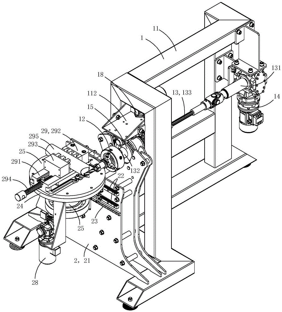
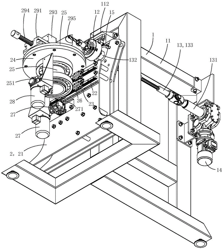
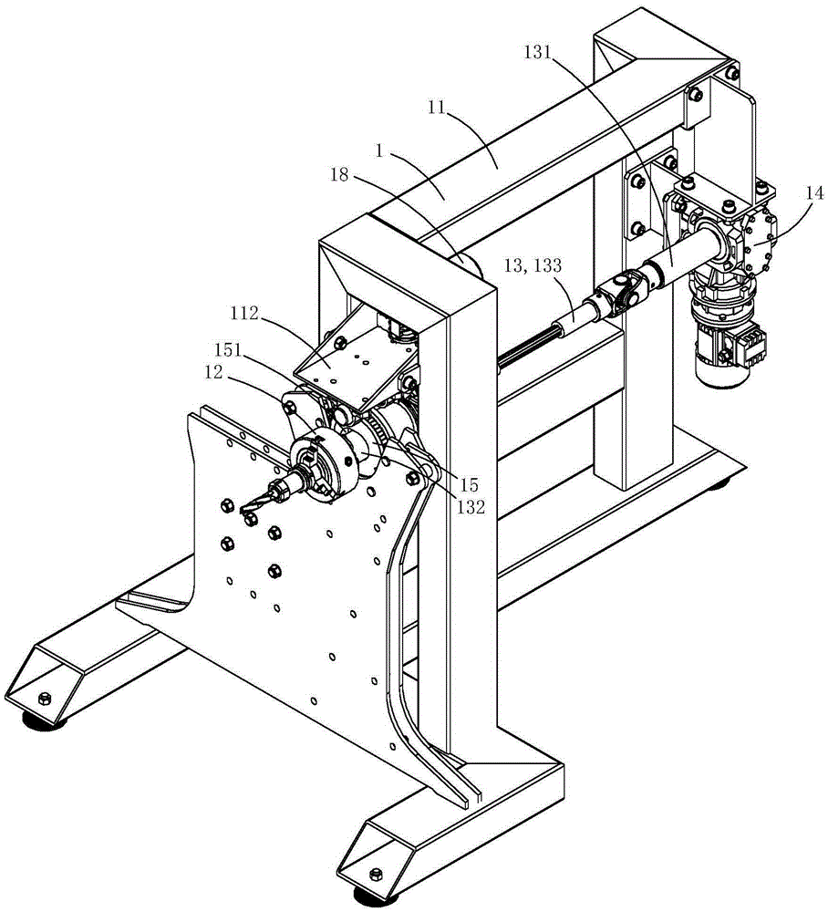
[0013] Figure 1 to Figure 6 One specific embodiment of the invention is shown.

[0014] This embodiment is a slotting machine, see Figure 1 to Figure 6 As shown, it includes a slotting machine body 1 and a tool assembly 2 arranged on the slotting machine body.

[0015] The slotting machine body includes a frame 11, a chuck 12, a main shaft 13 for driving the chuck to rotate, a main drive motor 14 for driving the main shaft to rotate, a limit gear 15 for limiting the swing position of the chuck, and a countershaft 16. The transmission wheel 17 fixedly arranged on the auxiliary shaft for driving the limit gear to rotate, and the auxiliary driving motor 18 for driving the auxiliary shaft to rotate; the auxiliary shaft is arranged along the horizontal line;

[0016] The main shaft is a oscillating main shaft, including a base shaft part 131 fixedly connected to the output shaft of the main drive motor, a working shaft part 132 for driving the chuck to rotate, and a linkage sha...


PUM


Abstract

The invention discloses a grooving machine. The grooving machine comprises a grooving machine body and a tool assembly. The grooving machine body comprises a rack, a chuck, a main shaft, a main driving motor, a limiting gear, an auxiliary shaft, a transmission wheel and an auxiliary driving motor. The main shaft is a swinging type main shaft and comprises a base shaft portion, a working shaft portion and a linkage shaft portion. The limiting gear is rotationally arranged on the rack. A kidney-shaped limiting hole is formed in the center of the limiting gear. The working shaft portion is located in the kidney-shaped limiting hole and swings in a reciprocating mode along the kidney-shaped limiting hole under driving of the main shaft. The tool assembly comprises a fixed board, horizontal sliding rails, a horizontal straight line type toothed rail, a work frame, a rotary table, guide rail bases, a horizontal drive motor, a rotary drive motor and a tool clamp fixedly arranged on the rotary table. The rotary center axis of the rotary table is in the direction of the plumb line. The horizontal drive motor drives the tool clamp to move in a reciprocating mode along the sliding rails. The rotary drive motor drives the tool clamp to rotate around the rotary center axis of the rotary table. The grooving machine can machine special grooves.

Description

technical field [0001] The invention belongs to the technical field of mechanical processing, and in particular relates to a slotting machine. Background technique [0002] The slotting machines currently on the market have relatively single functions, especially it is difficult to meet the drilling and milling processing of some special slots. Contents of the invention [0003] The purpose of the present invention is to provide a slotting machine with swing processing function, which can meet the slotting requirements of special holes. [0004] The technical solution for realizing the purpose of the present invention is: a slotting machine, including a slotting machine body and a tooling assembly arranged on the slotting machine body; the slotting machine body includes a frame, a chuck, and a tool for driving the chuck to rotate The main shaft, the main drive motor for driving the main shaft to rotate, the limit gear for limiting the swing position of the chuck, the au...

Claims


Application Information

Patent Timeline
IPC IPC(8): B23C3/28B23Q1/25
Inventor 刘开成
Owner CHUZHOU PINZHIDA ELECTRIC TECH
Why Eureka
Try Eureka