Automatic locking structure of adjusting screw rod for flow-adjustable metering pump

A technology for adjusting screw and flow measurement, which is applied to the components of the pumping device for elastic fluid, the pump, and the pump control. The effect of easy availability of parts

Active Publication Date: 2016-03-23
MILTON ROY IND SHANGHAI
View PDF5 Cites 1 Cited by
  • Summary
  • Abstract
  • Description
  • Claims
  • Application Information

AI Technical Summary

Problems solved by technology

A through groove 21 is opened on the side cover 2, and a locking ball 9 is arranged in the through groove 21, and a set screw 10 is also arranged in the through groove 21, and the set screw 10 is threadedly connected with the through groove 21, and the set screw When 10 is screwed inward, it drives the locking ball 9 to move downward, and presses the locking ball 9 into the thread groove of the adjusting screw 3 to realize the anti-loosening effect. When adjusting the adjusting screw 3, the set screw 10 must be loosened. To make the locking ball 9 break away from the thread groove of the adjusting screw 3, but if you forget to lock the set screw 10 after the adjustment is completed, the locking ball 9 will not automatically lock the adjusting screw 3 without the function of the set screw, which will make the adjustment The screw 3 moves with the reciprocating movement of the pump, which eventually causes the flow to be unstable

Method used


Image

  • Automatic locking structure of adjusting screw rod for flow-adjustable metering pump
  • Automatic locking structure of adjusting screw rod for flow-adjustable metering pump
  • Automatic locking structure of adjusting screw rod for flow-adjustable metering pump

Examples


Embodiment

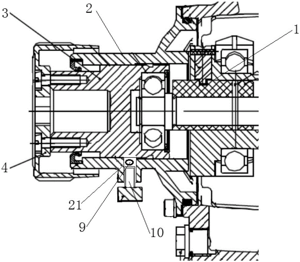
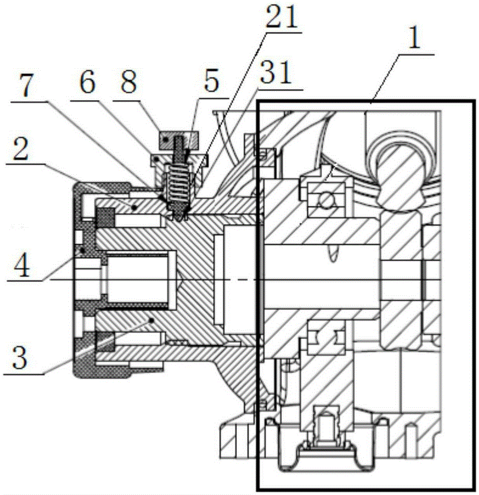
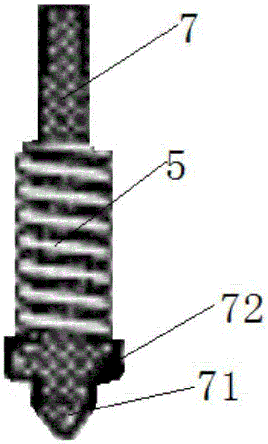
[0022] Such as figure 2 , image 3 As shown, the adjustable flow metering pump uses the automatic locking structure of the adjusting screw. The adjustable flow metering pump includes a driving end 1, a side cover 2, an adjusting screw 3 and an adjusting handle 4. The side cover 2 is connected with the driving end 1 to adjust The screw rod 3 is located inside the side cover 2, and is driven by threads with the side cover 2. The adjustment handle 4 is located outside the side cover 2 and connected with the adjustment screw rod 3. When the adjustment handle 4 is rotated, the adjustment handle 4 drives the adjustment screw rod 3 to move Finally adjust the eccentricity, and then adjust the flow rate of the adjustable flow metering pump. The automatic locking structure includes a spring 5, a spring cover 6 and a locking spring seat 7. The inner end of the locking spring seat 7 is the locking end, and the outer end is the free end. end, and the middle part is the guide rod for sett...


PUM


Abstract

The invention relates to an automatic locking structure of an adjusting screw rod for a flow-adjustable metering pump. The metering pump comprises a driving end, a side cover, an adjusting screw rod and an adjusting handle, wherein the adjusting screw rod is located in the side cover and performs transmission with the side cover through threads, and the adjusting handle is connected with the adjusting screw rod; when the adjusting handle is rotated, the adjusting handle drives the adjusting screw rod to move, the eccentric distance is finally adjusted, and flow of the metering pump is adjusted; the automatic locking structure comprises a spring, a spring gland and a locking spring seat, the inner end of the locking spring seat is a locking end, the outer end of the locking spring seat is a free end, a guide rod used for sleeving the spring is arranged in the middle of the locking spring seat, a through slot is formed in the side cover, the locking spring seat penetrates through the through slot in the side cover, the locking end of the locking spring seat is clamped in the adjusting screw rod, the guide rod of the locking spring seat is sleeved with the spring, and the spring is located in the through slot, the spring gland is connected to an opening of the through slot and compresses the spring, and the free end extends out of the outer side of the spring gland. Compared with the prior art, the automatic locking structure is simple in arrangement, good in locking effect and convenient to adjust.

Description

technical field [0001] The invention relates to an adjusting structure of an adjustable flow metering pump, in particular to an automatic locking structure of an adjusting screw used in an adjustable flow metering pump. Background technique [0002] Existing adjustable flow metering pumps such as figure 1 As shown, it includes a driving end 1, a side cover 2, an adjusting screw 3 and an adjusting handle 4. The side cover 2 is connected with the driving end 1. The adjusting screw 3 is located in the side cover 2, and is transmitted with the side cover 2 through threads. The adjustment handle 4 is located outside the side cover 2 and is connected with the adjustment screw 3. When the adjustment handle 4 is rotated, the adjustment handle 4 drives the adjustment screw 3 to move to finally adjust the eccentricity, and then adjust the flow of the adjustable flow metering pump. The existing adjustable flow metering pump is to lock the adjustment structure by the set screw. A thro...

Claims


Application Information

Patent Timeline
Patent Type & Authority Applications(China)
IPC IPC(8): F04B13/00F04B49/00F04B53/00
CPCF04B13/00F04B49/00F04B53/00
Inventor 柳玉萍孙林陆凯靳雪松陈建国
Owner MILTON ROY IND SHANGHAI
Why Eureka
Try Eureka