
Combined loading buckling test device for submarine pipeline complex load

A technology of complex load and joint loading, applied in the direction of measuring device, using stable bending force to test material strength, using stable torsion to test material strength, etc., can solve the problem that the value of bending moment cannot be changed, and various Joint action of loads, single external load, etc., to achieve the effect of a comprehensive analysis perspective

Active Publication Date: 2018-05-04
TIANJIN UNIV
View PDF5 Cites 1 Cited by
  • Summary
  • Abstract
  • Description
  • Claims
  • Application Information

AI Technical Summary

Problems solved by technology

[0005] 1. The external loads that can be simulated by deep-water pressure chambers at home and abroad are single, mainly due to the influence of axial tension or bending moment under the action of water pressure on the mechanical properties of submarine pipelines, and it is impossible to realize the partial load of full-scale pipelines under the joint action of multiple loads. Stability test
[0006] 2. The bending moment loading method can only fix the pipe fittings according to the bending moment before applying water pressure, put the fixing parts in the pressure chamber for testing, and cannot change the bending moment value during the test
[0007] 3. Torque load is an important factor that must be considered in pipe laying operations and oil pipelines. There are few torque tests for full-size pipe fittings at home and abroad.
[0008] There is a test device in China (such as patent application number: CN201110008538), which pioneered the test of a full-scale pipeline in China, but it is only a single application of external loads, and cannot realize the joint action of multiple loads

Method used


Image

  • Combined loading buckling test device for submarine pipeline complex load
  • Combined loading buckling test device for submarine pipeline complex load
  • Combined loading buckling test device for submarine pipeline complex load

Examples


Embodiment Construction

[0033] Below in conjunction with accompanying drawing, the specific embodiment of the present invention will be further described:

[0034] Such as

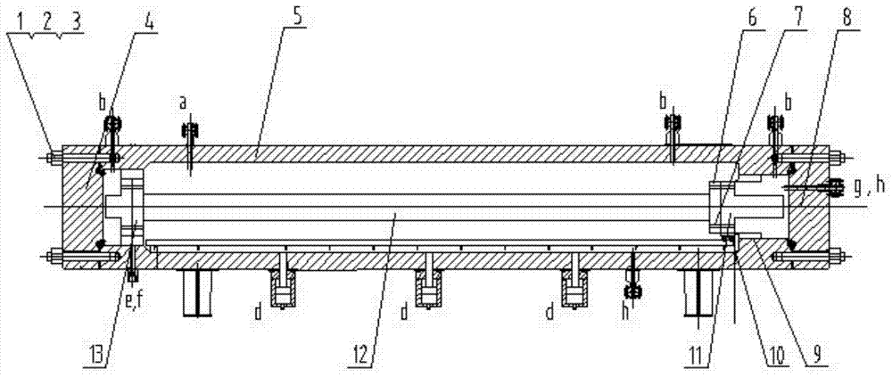
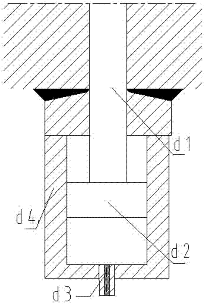
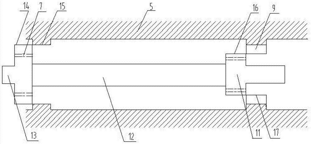
[0035] As shown in the figure, the combined loading buckling test device for deep-water submarine pipeline mainly includes: studs 2, front hatch cover 4, main cabin body 5, rear hatch cover 8, threaded ring cylinder 9, rear End flange 11, test pipe fitting 12, front end flange 13, safety valve a, drain b, pressure hole h, water injection port g, test circuit opening f, lateral hydraulic rod device d, etc. The front hatch 4 and the rear hatch 8 of the cabin are connected and sealed with the main cabin 5 by bolts 2, mainly composed of 16 bolts. The ring is waterproof and sealed, and the rear hatch includes a pressurization port h and a water injection port g. The test data of the pipe fittings in the cabin is transmitted to the data acquisition and processing system outside the cabin through the opening of the cabin. The front ha...


PUM


Abstract

The invention relates to a test device for complex loading and united loading buckling of a submarine pipeline. The test device is used for testing a test pipeline (12) and comprises a main cabin (5), a lateral hydraulic rod device d, a front-end flange (13), two sets of rear-end flanges (11) and circular cylinders (9) with threads, wherein the lateral hydraulic rod device d is used for applying bending moment to the test pipeline (12); the rear-end flanges (11) and the circular cylinders (9) are matched with each other on the threads; the thread matched with the front-end flange (13) is arranged on an inward bulge part at the front end of the main cabin (5); the first set of rear-end flange (11) and circular cylinder (9) with threads has a thread pitch of the thread identical to the thread pitch of the front-end flange and is called as category I; the second set of rear-end flange (11) and circular cylinder (9) with threads has the thread pitch of the thread different from the thread pitch of the front-end flange and is called as category II. The test device can be used for simulating the practical operation environment of the full-size submarine pipeline in the paving and service periods.

Description

technical field [0001] The invention relates to a combined loading buckling test device for a deep-water submarine pipeline, which can realize the joint action of axial tension, bending moment and torque load on a full-scale submarine pipeline. Background technique [0002] Energy security and the core competitiveness of the world economy are increasingly dependent on the utilization and development of marine resources. However, my country's offshore oil and gas exploration and development technology still has a large gap compared with the world's advanced level. It is necessary to accelerate the technological innovation of deep-sea oil and gas development and enter the "deep-sea era". The strategy of marine power has gradually risen to the national will. [0003] Among them, the design and construction of deep-sea oil pipelines and related technologies are the key to the development of deep-sea oil and gas resources. The safe operation of oil pipelines is an important guar...

Claims


Application Information

Patent Timeline
Patent Type & Authority Patents(China)
IPC IPC(8): G01N3/10G01N3/20G01N3/22
CPCG01N3/10G01N3/20G01N3/22G01N2203/0026G01N2203/0048
Inventor 余建星段晶辉余杨孙震洲樊志远吴梦宁
Owner TIANJIN UNIV
Learn More