
Spherical surface-engaged universal multi-section synchronous transmission mechanism

A synchronous transmission and meshing technology, applied in the directions of manipulators, claw arms, manufacturing tools, etc., can solve the problems of inability to realize multi-joint synchronous motion, inability to realize spatial motion, and increased structural complexity, and achieve a small number of driving sources and reduce control. Difficulty, the effect of reducing the drive load

Inactive Publication Date: 2016-03-30
TONGJI UNIV
View PDF7 Cites 2 Cited by
  • Summary
  • Abstract
  • Description
  • Claims
  • Application Information

AI Technical Summary

Problems solved by technology

In addition, each motor and reducer can only drive one joint. If multiple joints are to be driven, multiple motors and reducers are required, which not only greatly increases the load of the upper drive, but also wastes resources and greatly increases the difficulty of control.
In the drive of the mechanical arm, there is another kind of wire rope transmission. This driving method can only realize the planar movement of the mechanical arm. If the spatial movement of the mechanical arm is to be realized, the complexity of the structure will be greatly increased.
The above-mentioned driving method is generally driven independently by each joint, and cannot realize the synchronous motion of multiple joints, that is, to drive multiple joints through one driving source
[0003] The Chinese invention patent with the publication number 101670583A disclosed a multi-joint synchronous bending mechanical arm based on connecting rod transmission on March 17, 2010. This invention patent can realize the movement in the plane of the mechanical arm, but cannot realize the spatial movement

Method used


Image

  • Spherical surface-engaged universal multi-section synchronous transmission mechanism
  • Spherical surface-engaged universal multi-section synchronous transmission mechanism
  • Spherical surface-engaged universal multi-section synchronous transmission mechanism

Examples


Embodiment 1

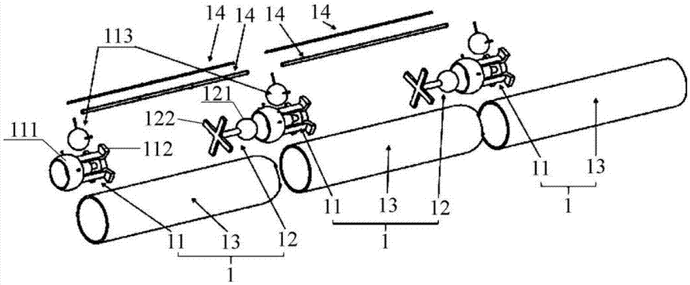
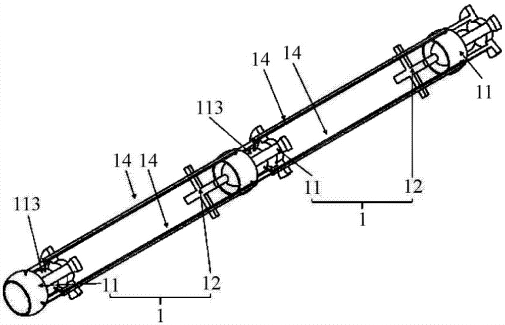
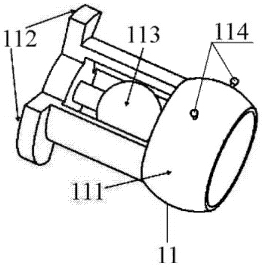
[0031] A spherical meshing universal multi-joint synchronous transmission mechanism, including three boom joints 1, such as Figure 1 to Figure 6 As shown, the specific structure is:

[0032] The arm sections 1 are connected sequentially. The arm sections 1 at the head end and the middle end include a front connecting piece 11 and a rear end connecting piece 12. The arm section 1 at the rear end includes a front connecting piece 11. The arm section 1 also includes an arm shell 13. Part 11 is arranged on the front end of arm shell 13, and rear-end connecting piece 12 is arranged on the rear end of arm shell 13, and front-end connecting piece 11 comprises a sphere or a spherical cap, and rear-end connecting piece 12 comprises and front-end connecting piece 11 forms spherical surface Engaged spherical crown shells or spheres; when the number of arm sections 1 is more than one, adjacent arm sections 1 are connected through the engagement between the spheres and the spherical crown...


PUM


Abstract

The invention relates to the field of joints having more than one degree of angular degree and specifically relates to a spherical surface-engaged universal multi-section synchronous transmission mechanism. The spherical surface-engaged universal multi-section synchronous transmission mechanism comprises at least one arm section (1), and is characterized in that: each arm section (1) comprises at least one of a front-end connecting piece (11) and a rear-end connecting piece (12), and also an arm shell (13); the rear-end connecting piece (12) is arranged on a rear end of the arm shell (13); the front-end connecting piece (11) comprises a sphere or a spherical crown shell; and the rear-end connecting piece (12) comprises a spherical crown shell or a sphere in spherical surface engagement with the front-end connecting piece (11). The spherical surface-engaged universal multi-section synchronous transmission mechanism has the advantages of decrease of driving sources, reduction of driving loads, reduction of control difficulty, and wide application range.

Description

technical field [0001] The invention relates to the field of joints with more than one degree of freedom, in particular to a spherical meshing universal multi-joint synchronous transmission mechanism. Background technique [0002] In some multi-section mechanical structures, such as in the mechanical arm, the drive of each joint is usually driven by a motor accelerator and decelerator. Become the load driven by the upper stage. In addition, each motor and reducer can only drive one joint. If multiple joints are to be driven, multiple motors and reducers are required, which not only greatly increases the load of the upper drive, but also wastes resources and greatly increases the difficulty of control. In the driving of the mechanical arm, there is another kind of wire rope transmission. This driving method can only realize the planar movement of the mechanical arm. If the spatial movement of the mechanical arm is to be realized, the complexity of the structure will be great...

Claims


Application Information

Patent Timeline
IPC IPC(8): B25J18/04
CPCB25J18/04
Inventor 熊肖磊吴青龙周奇才陈明阳
Owner TONGJI UNIV
Learn More