Snap joint type lead sealing electronic unsealing device

An unsealer and buckle-type technology, which is applied in the field of buckle-type lead-sealed electronic unsealers, can solve the problems that conventional tools are difficult to remove, the electric meter is easily damaged, and the seal is small

Inactive Publication Date: 2016-03-30
STATE GRID XINJIANG ELECTRIC POWER CO URUMQI ELECTRIC POWER SUPPLY CO +1
View PDF4 Cites 1 Cited by
  • Summary
  • Abstract
  • Description
  • Claims
  • Application Information

AI Technical Summary

Problems solved by technology

[0002] Because the buckle-type lead seal is round, it is embedded in the screw for sealing. Since the seal is relatively small and the seal cover is thin, it is difficult to remove it with conventional tools such as pliers and clips.
When the staff is performing the unsealing operation, sometimes it is difficult to dismantle it smoothly for a minute or two. At present, there are no supporting tools to facilitate the unsealing operation
Violent opening is required in the unpacking process, which is easy to damage the structure of the meter and the meter box body

Method used


Image

  • Snap joint type lead sealing electronic unsealing device

Examples


specific Embodiment approach

[0008] Specific implementation methods: the present application is not limited by the following examples, and the specific implementation manners can be determined according to the technical solutions of the application and actual conditions.

Embodiment

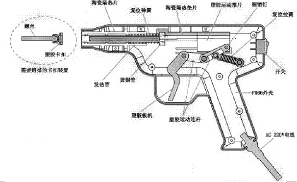
[0009] Example: as figure 1 As shown, the buckle type lead-sealed electronic unsealing device includes a gun body, and the gun body is divided into a grip cavity, a gun barrel, and a gun chamber. Ceramic heat insulating sheets are arranged on the inner wall of the gun barrel to form a heat insulation channel. A trigger is arranged on the side communicating with the gun bore, and the trigger is connected to the first connecting rod, and a second connecting rod is connected behind the first connecting rod, and the rear end of the second connecting rod is connected to a certain shaft, and the fixed shaft It is arranged on a slide block, and the middle part of the second connecting rod is connected with a return spring. The slider slides left and right in the slideway arranged in the gun chamber, the front side of the slider is provided with a heat-insulating connecting rod connected to the heating pipe, the front end of the heat-insulating connecting rod is clamped with the rear ...


PUM


Abstract

The invention relates to a snap joint type lead sealing electronic unsealing device. The snap joint type lead sealing electronic unsealing device comprises a gun body which is divided into a holding cavity, a gun barrel and a bore; a thermal insulation channel composed of ceramic thermal insulation sheets is arranged at the inner wall of the gun barrel, and a trigger is arranged on the communication side of the holding cavity and the bore and movably connected with a first connecting rod; and a second connecting rod is movably connected behind the first connecting rod, the back end of the second connecting rod is movably connected with a fixed shaft which is arranged on a sliding block, and a reset spring is connected to the middle portion of the second connecting rod. The sliding block slides left and right in a sliding way arranged in the bore, a thermal insulation connecting rod connected with a heating pipe is arranged on the front side of the sliding block, and the front end of the thermal insulation connecting rod and the back end of the heating pipe are connected in a clamped manner; and the heating pipe can stretch out and draw back along the thermal insulation channel, and the heating pipe is connected with a switch and an external power circuit. By means of the snap joint type lead sealing electronic unsealing device, a hot melting principle is adopted for melting a seal at a moment so as to achieve the unsealing effect, it can be guaranteed that unsealing operation is completed within three seconds, the snap joint type lead sealing electronic unsealing device is convenient and rapid, the unsealing efficiency is greatly improved, and the self structure of a watch is not damaged.

Description

technical field [0001] This application belongs to a buckle-type lead seal electronic unsealing device. Background technique [0002] Since the buckle-type lead seal is round in shape, it is sealed by being embedded in a screw. Since the seal is relatively small and the seal cover is thin, it is difficult to remove it with conventional tools such as pliers and clips. When the staff is performing the unsealing operation, sometimes it is difficult to remove it smoothly for a minute or two. At present, there are no supporting tools to facilitate the unsealing operation. Violent opening is required in the unpacking process, which is easy to damage the structure of the meter and the meter box body. Contents of the invention [0003] The purpose of this application is to propose a snap-on lead seal electronic unsealing device that can quickly unseal the snap-on lead seal. [0004] The purpose of this application is achieved in this way: the buckle-type lead-sealed electronic u...

Claims


Application Information

Patent Timeline
Patent Type & Authority Applications(China)
IPC IPC(8): B65B69/00
CPCB65B69/0066
Inventor 黄琰李航张远周宜刘旭程雪峰马建宁李昕原春亮郭健锋周海涛李艇张笑海胡慧敏韩生龙
Owner STATE GRID XINJIANG ELECTRIC POWER CO URUMQI ELECTRIC POWER SUPPLY CO
Why Eureka
Try Eureka