
Fan device with oil bearing

A technology of bearings and fans, applied in the field of fan devices, can solve problems such as difficult control of dispensing process, stuck, affecting normal assembly, etc.

Active Publication Date: 2016-03-30
ASIA VITAL COMPONENTS CHENGDU
View PDF7 Cites 0 Cited by
  • Summary
  • Abstract
  • Description
  • Claims
  • Application Information

AI Technical Summary

Problems solved by technology

[0007] 1. The dispensing process is not easy to control, which will cause abnormal noise and cause the axis to be stuck;
[0008] 2. Interference tight fit will squeeze the shaft center, affect the normal assembly and cause the shaft center to be stuck

Method used


Image

  • Fan device with oil bearing
  • Fan device with oil bearing
  • Fan device with oil bearing

Examples


Embodiment Construction

[0047] The above-mentioned purpose of the present invention and its structural and functional characteristics will be described according to the preferred embodiments of the accompanying drawings.

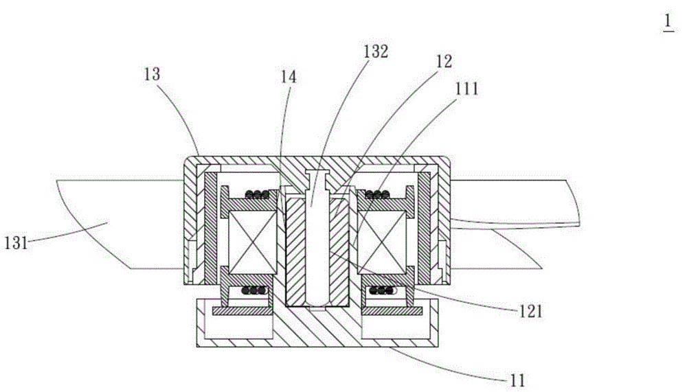
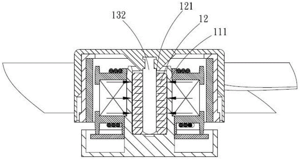
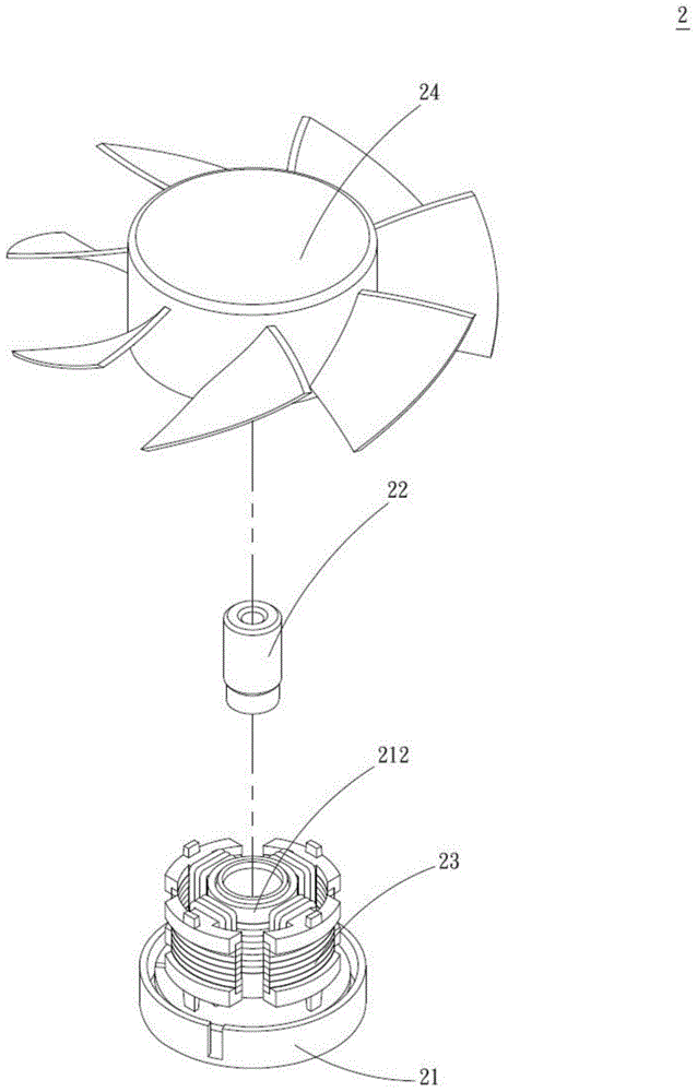
[0048] see Figure 2A and 2B As shown in and 2C, it is a three-dimensional exploded view, a three-dimensional disassembled sectional view and a three-dimensional combined sectional view of the first preferred embodiment of the present invention. The fan device 2 includes a base 21, an oil bearing 22, a stator group 23 and a Fan wheel 24, wherein one side of the base 21 has a middle tube 211 and a shaft tube 212 extending from the middle tube 211 to one side, the shaft tube 212 has a bearing hole 2121 inside, and the middle tube 211 is opposite to the bearing hole There is at least one butt joint 2111 at the position 2121, the butt joint 2111 is a plurality of grooves recessed on the surface of the middle tube 211 in this embodiment, but not limited thereto, and the oil-impregnated...


PUM


Abstract

The invention provides a fan device with an oil bearing. The fan device comprises a base and the oil bearing, wherein the base is provided with a middle pipe and a shaft barrel extending from the middle pipe to one side; a bearing hole is formed in the shaft barrel; at least one butt joint portion is arranged in the position, opposite to the bearing hole, of the middle pipe; the oil bearing is provided with at least one assembling-connecting portion assembled on the butt joint portion. Therefore, the oil bearing is fixedly arranged in the bearing hole through mutual assembly of the assembling-connecting portions and the butt joint portions, and the situation that operation is affected by close-fitting interference and difficult control over dispensing can be avoided.

Description

technical field [0001] The invention relates to a fan device of an oil-impregnated bearing, in particular to an oil-impregnated bearing fan device which can effectively fix the oil-impregnated bearing and can avoid affecting operation due to interference tight fitting and uncontrollable glue dispensing. Background technique [0002] Press, the use of electronic information products (such as: computers, etc.) is becoming more and more popular and more widely used. Due to the rapid development of electronic information industry technology driven by demand, electronic information is developing towards the trend of increasing computing speed and increasing access capacity. The parts and components in the aforementioned electronic information products are often accompanied by high temperature during high-speed operation. [0003] Taking a computer mainframe as an example, the heat generated by its internal central processing unit (CPU) accounts for the majority. In addition, when...

Claims


Application Information

Patent Timeline
IPC IPC(8): F04D29/056
Inventor 尹冠尘
Owner ASIA VITAL COMPONENTS CHENGDU
Learn More