
Bending press

A bending pressure and press technology, which is applied in the field of bending presses, can solve the problems of time-consuming equipment solutions, complex bending machines, etc., and achieve the effect of saving time and personnel consumption.

Active Publication Date: 2018-04-17
BYSTRONIC LASER
View PDF15 Cites 0 Cited by
  • Summary
  • Abstract
  • Description
  • Claims
  • Application Information

AI Technical Summary

Problems solved by technology

In the prior art, it was necessary to be able to position the tool precisely relative to the tool holder, which resulted in a complex and time-consuming equipping solution for the bending machine

Method used


Image

  • Bending press
  • Bending press
  • Bending press

Examples


Embodiment Construction

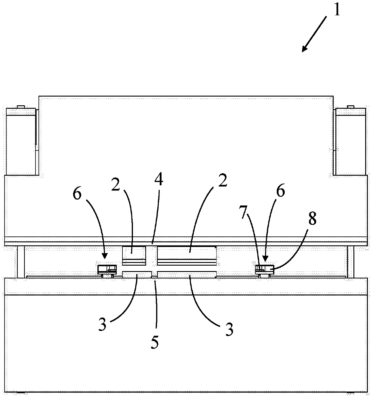
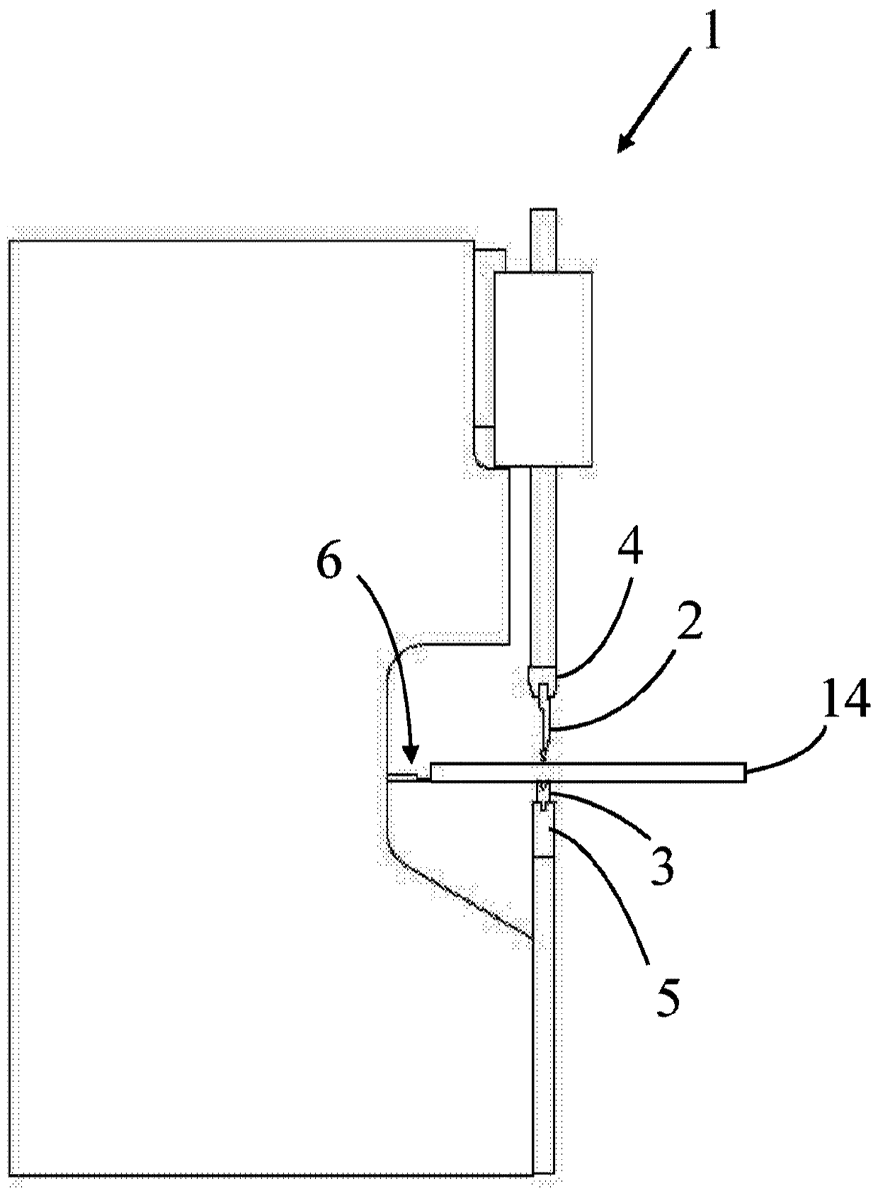
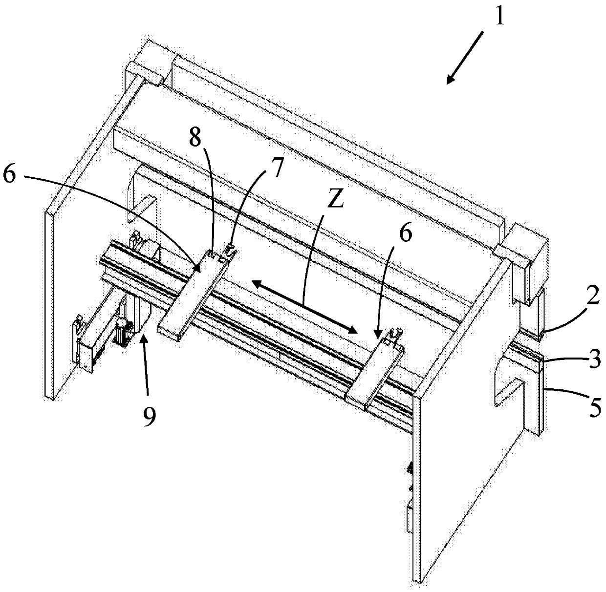
[0091] figure 1 Shown is a bending press 1 for bending workpieces with an upper tool 2 (punch) and a lower tool 3 (die), a tool holder 4 into which the upper tool 2 is inserted, and a tool holder 4 into which the lower tool 3 is inserted. Tool holder 5. The length of the tool holder 4 , 5 along the Z axis (ie parallel to the bending line) is dimensioned such that a plurality of upper and lower tools 2 , 3 can be mounted and fixed side by side in the tool holder 4 , 5 . This situation is Figure 6 is shown in , where two lower tools 3 are accommodated in a tool holder 5 .

[0092] The upper tool 2 and the lower tool 3 can be fixed in different positions within the respective tool holder 4 , 5 . This means that the tools can be arranged differently in the direction of the Z-axis relative to the corresponding tool holder.

[0093] The bending press 1 has at least one stop gauge (Anschlag) 6 for holding the workpiece 14 ( figure 2 ) is located inside the bending press 1, whe...


PUM


Abstract

The invention relates to a bending press (1) for bending workpieces (14), comprising: an upper tool (2) and a lower tool (3); a tool holder (4) in which the upper tool (2) is mounted ), and a tool holder (5) in which the lower tool (3) is mounted, wherein the upper tool (2) and the lower tool (3) can be fixed in different positions within the respective tool holder (4, 5) ; a control device (13) for controlling the bending press (1); a sensing device (8), which is connected to the control device (13); The workpiece is positioned inside the machine (1), wherein the stop gauge (6) can be moved relative to the tool (2, 3) by means of a drive device (9) actuated by a control device (13). The sensing device (8) is configured for contactless detection of the position of the upper tool (2) and the lower tool (3) inside the bending press (1), and the control device (13) is configured to interact with The positions of the upper tool ( 2 ) and the lower tool ( 3 ) detected by the sensor device ( 8 ) are adapted to the movement sequence for positioning the stop gauge ( 6 ) relative to the tools ( 2 , 3 ).

Description

technical field [0001] The invention relates to a bending press according to the preamble of claim 1 and to a method for bending workpieces with a bending press according to claim 8 . Background technique [0002] The selection and arrangement of tools in bending presses (also called flanging presses or bending machines) is largely performed manually and only partially assisted by a mechanical controller. For this purpose, a bending plan is specified which estimates the product-specific upper tool and lower tool as well as the theoretical position of the upper tool and lower tool. But what cannot be monitored is whether the tool is used or has been used in the machine. Additionally, tools may be installed in potentially dangerous locations that do not correspond to the process. [0003] However, the tool needs to be positioned precisely in order to carry out the bending process with high quality and to adjust the backstop fingers or the robot accordingly. Corresponding po...

Claims


Application Information

Patent Timeline
Patent Type & Authority Patents(China)
IPC IPC(8): B21D5/00B21D5/02
CPCB21D5/002B21D5/02B21D5/0281B21D11/22B21D5/0209B21D43/003B21D43/26B21D5/0272
Inventor 拉尔斯·沃尔达斯基
Owner BYSTRONIC LASER
Learn More