Machine tool with rotary clamp assembly

A rotary, component technology, used in clamping, manufacturing tools, metal processing mechanical parts, etc., can solve the problem of cumbersome fixing operation, avoid manual clamping, realize automatic conversion, and reduce production and manufacturing costs.

Pending Publication Date: 2021-11-23
邳州市耿联军机械制造厂
View PDF8 Cites 2 Cited by
  • Summary
  • Abstract
  • Description
  • Claims
  • Application Information

AI Technical Summary

Problems solved by technology

When processing some circular parts, the workpiece needs to be rotated. Before processing, the parts need to be positioned and then manually fixed. The fixing operation is cumbersome.

Method used


Image

  • Machine tool with rotary clamp assembly
  • Machine tool with rotary clamp assembly
  • Machine tool with rotary clamp assembly

Examples


Embodiment 1

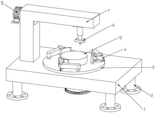
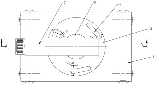
[0030] refer to Figure 1~Figure 4 In this embodiment, a machine tool with a rotary fixture assembly is proposed, which is used to clamp and rotate a workpiece 5 for processing. The machine tool with a rotary fixture assembly includes: a workbench 1, a rotating Table 3, processing assembly 6, transmission member and first motor 14.

[0031] The workbench 1 forms a support platform. The four corners of the bottom of the workbench 1 are provided with support legs 2. The bottom of the support legs 2 is fixedly connected with a backing plate. The support legs 2 support the workbench 1 to a specified height. The setting of the backing plate increases the support Stability of leg 2 support. The backing plate is provided with a through hole, and the setting of the through hole is convenient to fix the supporting leg 2 by screws, thereby fixing the machine tool.

[0032] The turntable 3 is rotatably connected to the workbench 1. The turntable 3 is a cylindrical structure, and the se...

Embodiment 2

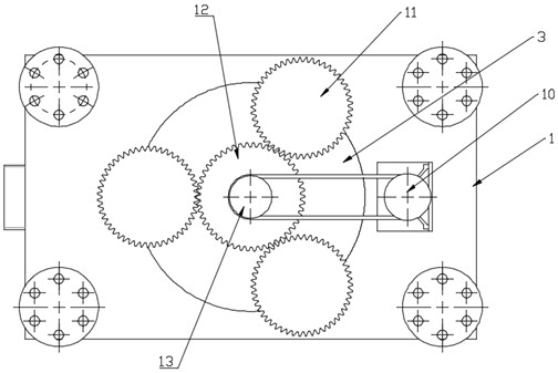
[0038] refer to Figure 5 , the clamping member 4 includes a rotating rod 20, a clamping rod 21 and a clamping plate 23, the rotating rod 20 is rotatably connected to the upper surface of the turntable 3, the rotating rod 20 is coaxially fixedly connected with the driven gear 11, and rotates The top of the rod 20 is fixedly connected to one end of the clamping rod 21, the other end of the clamping rod 21 is rotatably connected to a rotating rod 22, and one end of the rotating rod 22 is connected to a clamping plate 23, and the rotation of the rotating rod 22 drives the clamping rod 21 to rotate , so as to drive the clamping plate 23 to move to clamp the workpiece 5, thereby facilitating the fixing of the workpiece 5. One end of the rotating rod 22 is fixedly connected with a connecting rod 26, the lower end of the connecting rod 26 is connected with a protrusion, the upper surface of the rotating table 3 is provided with a guide groove, and the protrusion slides and nests insi...


PUM


Abstract

The invention relates to the technical field of machining, and discloses a machine tool with a rotary clamp assembly. The machine tool comprises a workbench, a rotating table, a plurality of clamping parts, a first motor, a support frame, a transverse driving part, a vertical driving part and a controller, wherein the rotating table is rotationally connected to the workbench; the plurality of clamping parts are circumferentially and rotatably connected to the upper surface of the rotating table and rotate outwards to be reset through reset parts, a rotating shaft is rotatably arranged at the bottom of the rotating table, and the rotating shaft is connected with the clamping parts through transmission parts; the first motor is mounted on the workbench, connected with the rotating shaft through a connecting structure and used for driving the rotating shaft to rotate; the support frame is fixedly connected to the workbench, a machining assembly is arranged on the support frame, and the machining assembly is used for machining a workpiece placed on the rotating table; the transverse driving part is connected with the machining assembly and used for transversely moving the machining assembly; and the vertical driving part is connected with the machining assembly and used for driving the machining assembly to move vertically . Through cooperation of the rotating shaft and the clamping parts, clamping of the workpiece is automatically converted into rotation of the rotating table.

Description

technical field [0001] The invention relates to the technical field of mechanical processing, in particular to a machine tool with a rotary clamp assembly. Background technique [0002] With the development of science and technology and the progress of society, what can be witnessed most is the use of various modern equipment in life, and the development of science and technology is indispensable for machine tools. A machine tool is a machine that processes metal blanks into machine parts. It is a machine that manufactures machines, so it is also called a machine tool or a machine tool, and is customarily referred to as a machine tool. There are many ways to process mechanical parts in modern machinery manufacturing: in addition to cutting, there are also casting, forging, welding, stamping, extrusion, etc. The final machining is done by cutting on the machine tool. When some circular parts are processed, the workpiece needs to be rotated and processed. Before processing, ...

Claims


Application Information

Patent Timeline
Patent Type & Authority Applications(China)
IPC IPC(8): B23Q1/01B23Q3/06B23Q7/02B23Q5/40
CPCB23Q1/015B23Q3/06B23Q7/02B23Q5/40
Inventor 耿联军孙振耿磊
Owner 邳州市耿联军机械制造厂
Why Eureka
Try Eureka