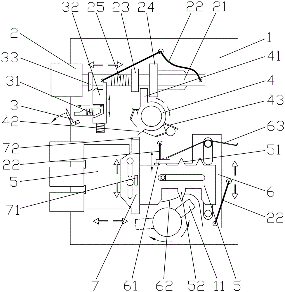
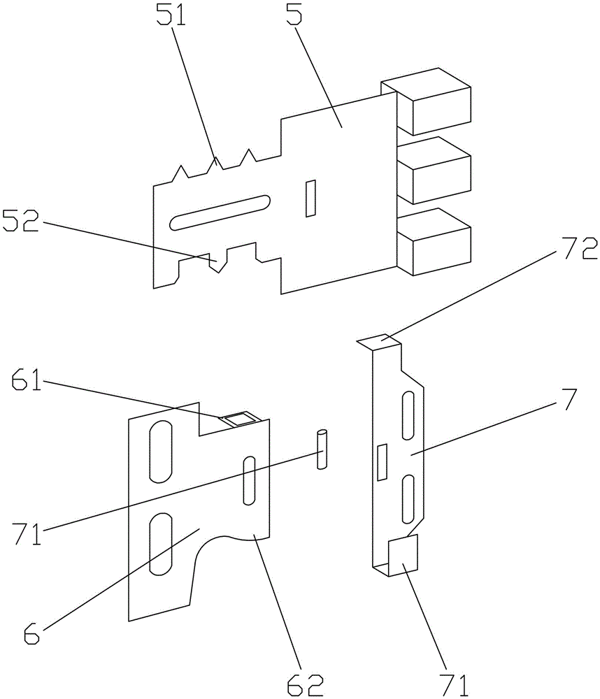
Mute door lock

A door lock and mute technology, which is applied in the direction of building locks, buildings, building structures, etc., can solve the problems of noise, high environmental mute requirements, and reduce the movement speed of the transmission mechanism, so as to achieve the effect of reducing noise

Inactive Publication Date: 2016-04-06
胡洪芳
View PDF6 Cites 0 Cited by
  • Summary
  • Abstract
  • Description
  • Claims
  • Application Information

AI Technical Summary

Problems solved by technology

[0002] In some special occasions, such as wards, etc., the requirements for quietness of the environment are high, and the sound generated by opening and closing the door is enough to become a noise source. When it pops up, it collides with the lock plate or other similar parts, which will make noise. For example, when the deadbolt is outside, it often needs to be pushed and pulled with a certain force to close the door. If the force is too large, it will hit the door frame due to inertia, resulting in noise. , and for example, when turning the key to unlock and let go to close the door, some components of the door lock, such as the deadbolt, will quickly reset under the action of the return spring, and a loud impact sound will also be issued
A designer designed a door lock. For details, please refer to the "Silent Magnetic Lock Body" with patent number 201510539163.1, which mentions the sound-absorbing stud and a sound-absorbing rubber sleeve, and the rear side is provided with cushioning foam. Designs such as solid-buckle box magnets and square tongue magnets attract each other to achieve silence, but these structures are not only costly, but also cannot fundamentally solve the problem of noise generated by impact; for example, the patent number is 201210143801.4 " "Mute door lock body", it is mentioned that the surface of the lock tongue is attached to the mute rubber ring, and the use of buffers such as springs reduces the movement speed of the transmission mechanism, etc., and the above-mentioned impact problems cannot be avoided.

Method used


Image

  • Mute door lock
  • Mute door lock

Examples


Embodiment Construction

[0017] In order to make the purpose, technical solution and advantages of the present application clearer, the present invention will be further described in detail below in conjunction with the accompanying drawings and embodiments. In the ensuing description some specific details are referred to for a thorough understanding of the present invention. While the present invention may still be practiced without these specific details, the descriptions and representations herein are used by those skilled in the art to effectively convey the substance of their work to others skilled in the art. In addition, it should be noted that, for the description about the orientation mentioned in the following description, those skilled in the art should not understand it as a technology outside the scope of protection of the present application when they make simple adjustments to the above directions without creativity. It should be understood that the specific embodiments described here a...


PUM


Abstract

The invention discloses a mute door lock. The mute door lock comprises a lock rack, a lock tongue bar connected with a lock tongue and a lock head linkage part which is in linkage with the lock tongue bar. A lock pull rope connected with the lock rack is disposed on the lock tongue bar and / or the lock head linkage part. According to the mute door lock, through reasonable structural improvement, especially the pull rope design, impact does not directly occur when the lock tongue returns or other parts are reset, and noise generated during locking and unlocking of the door lock is greatly lowered; besides, through the design that a contact block is in linkage with the lock tongue, the lock tongue is retracted in the door opened state and extends out when a door is closed in place, so that the impact sound generated when the lock tongue impacts on a door frame during door closing is avoided, and the noise of the door lock is further lowered; accordingly, the true mute effect is achieved.

Description

technical field [0001] The invention relates to the technical field of door locks, in particular to a door lock with less noise. Background technique [0002] In some special occasions, such as wards, etc., the requirements for quietness of the environment are high, and the sound generated by opening and closing the door is enough to become a noise source. When it pops up, it collides with the lock plate or other similar parts, which will make noise. For example, when the deadbolt is outside, it often needs to be pushed and pulled with a certain force to close the door. If the force is too large, it will hit the door frame due to inertia, resulting in noise. , and for example when turning the key to unlock and let go of the door when closing the door, some components of the door lock, parts such as the dead bolt reset quickly under the effect of the back-moving spring, and a larger impact sound will be sent equally. A designer designed a door lock. For details, please refer...

Claims


Application Information

Patent Timeline
IPC IPC(8): E05B15/00E05B15/10
CPCE05B15/00E05B15/101
Inventor 胡洪芳
Owner 胡洪芳
Why Eureka
Try Eureka