A battery pack voltage acquisition board tooling tester

A technology of voltage acquisition board and battery pack, which is applied in the direction of instruments, measuring electronics, measuring devices, etc., can solve the problems of low efficiency and poor detection reliability, and achieve the effects of simple circuit structure, improved detection efficiency, and reliable methods

Inactive Publication Date: 2018-03-27
HEILONGJIANG UNIV
View PDF5 Cites 0 Cited by
  • Summary
  • Abstract
  • Description
  • Claims
  • Application Information

AI Technical Summary

Problems solved by technology

[0004] The invention aims to solve the problem of low efficiency and poor detection reliability of the fault detection method for the existing battery pack voltage acquisition board in the production and debugging stages. The invention provides a tooling tester for the battery pack voltage acquisition board

Method used


Image

  • A battery pack voltage acquisition board tooling tester
  • A battery pack voltage acquisition board tooling tester
  • A battery pack voltage acquisition board tooling tester

Examples


specific Embodiment approach 1

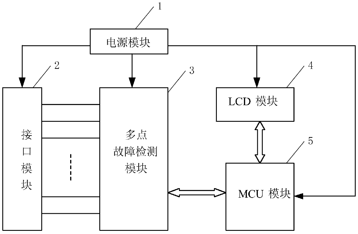
[0032] Specific implementation mode one: see figure 1 and 2 Describe this embodiment mode, a kind of battery pack voltage acquisition board tooling tester described in this embodiment mode, it comprises power supply module 1, interface module 2, multi-point fault detection module 3, LCD module 4 and MCU module 5;

[0033] The power supply module 1 is used to provide power to the interface module 2, the multi-point fault detection module 3, the LCD module 4 and the MCU module 5;

[0034] The interface module 2 is used to connect with the battery pack voltage acquisition signal input terminal on the voltage acquisition board to be measured;

[0035] The multi-point fault detection module 3 is used to perform fault detection on multiple points on the voltage acquisition board to be measured through the interface module 2, and send a fault detection signal;

[0036] The MCU module 5 is used to control the multi-point fault detection module 3, receive and process the fault detect...

specific Embodiment approach 2

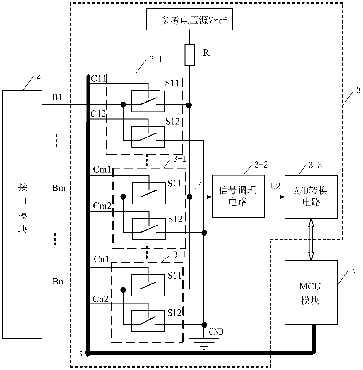
[0039] Specific implementation mode two: see figure 1 and 2 This embodiment is described. The difference between this embodiment and the battery pack voltage acquisition board tooling tester described in the first embodiment is that the multi-point fault detection module 3 includes n fault detection units 3-1, piezoresistor R, signal conditioning circuit 3-2 and A / D conversion circuit 3-3; n is a positive integer greater than or equal to 2;

[0040] The data signal input terminals of the 1st to nth fault detection units 3-1 are respectively connected with n battery pack voltage acquisition signal input terminals on the voltage acquisition board to be tested,

[0041] The first data signal output end of each fault detection unit 3-1 is connected with one end of the voltage dividing resistor R and the data signal input end of the signal conditioning circuit 3-2 at the same time, and the data signal output end of the signal conditioning circuit 3-2 is connected with A The data ...

specific Embodiment approach 3

[0047] Embodiment 3: The difference between this embodiment and the tooling tester for a battery pack voltage acquisition board described in Embodiment 2 is that each fault detection unit 3-1 includes a detection switch S11 and a detection switch S12;

[0048] The control signal input terminals of the detection switch S11 and the detection switch S12 are both used to receive the control signal output by the MCU module 5;

[0049] One end of the detection switch S11 and one end of the detection switch S12 are simultaneously connected to a data signal output end of the interface module 2,

[0050] The other end of the detection switch S11 is used as the first data signal output end of the fault detection unit 3-1,

[0051] The other end of the detection switch S12 is used as the second data signal output end of the fault detection unit 3-1,

[0052] One end of the detection switch S11 is the data signal input end of the fault detection unit 3-1.


PUM


Abstract

The invention relates to a cell set voltage acquisition board tool tester, belongs to the electric automobile or large power energy storage power supply cell management system application field and solves problems of low fault detection efficiency and poor detection reliability in the production and debugging stage of cell set voltage acquisition boards in the prior art. The tool tester comprises a power source module, an interface module, a multi-point fault detection module, an LCD module and an MCU module, wherein the power source module is used for providing electric energy for the interface module, the multi-point fault detection module, the LCD module and the MCU module, the interface module is used for connecting with a cell set voltage acquisition signal input end of a to-be-detected voltage acquisition board, the multi-point fault detection module is used for carrying out fault detection on multiple points of the to-be-detected voltage acquisition board through the interface module and sending a fault detection signal, and the MCU module is used for controlling the multi-point fault detection module, receiving and processing the fault detection signal and sending the fault detection signal processing result. The cell set voltage acquisition board tool tester is used for detecting cell set voltage acquisition boards.

Description

technical field [0001] The invention belongs to the application field of battery management systems for electric vehicles or high-power energy storage power supplies. Background technique [0002] The voltage acquisition board of the electric vehicle battery management system mainly realizes the functions of single battery voltage acquisition, temperature acquisition and control, and communication with the main board. Among them, the single battery voltage acquisition is the most important and basic function of the voltage acquisition board. The battery voltage acquisition input port is connected to the battery pack in the battery box through the wiring harness to realize the single battery voltage acquisition function. The battery pack voltage acquisition input circuit of the voltage acquisition board is generally composed of an RC filter circuit, a diode protection circuit, and an equalization circuit for energy consumption controlled by a MOS tube. However, during the pr...

Claims


Application Information

Patent Timeline
Patent Type & Authority Patents(China)
IPC IPC(8): G01R31/00G01R31/02
CPCG01R31/00G01R31/50
Inventor 王国凤魏廷库
Owner HEILONGJIANG UNIV
Why Eureka
Try Eureka