Star sensor optical imaging system for attitude determination of deep space exploration vehicle

An optical imaging system and deep-space detection technology, applied in the field of optical systems, can solve the problems of prolonged integration time of dynamic motion imaging, inapplicability to the field of attitude determination, and slow attitude determination of satellites, so as to reduce procurement difficulty, manufacturing cost, and energy consumption. The effect of high concentration and improved positioning accuracy

Active Publication Date: 2018-06-29
CHANGCHUN INST OF OPTICS FINE MECHANICS & PHYSICS CHINESE ACAD OF SCI
View PDF4 Cites 0 Cited by
  • Summary
  • Abstract
  • Description
  • Claims
  • Application Information

AI Technical Summary

Problems solved by technology

This will lead to disadvantages such as low incident light energy received by the image detector per unit time, prolonged dynamic motion imaging integration time, slow image refresh rate, and slow speed of satellite attitude determination when observing targets such as faint small stars in deep space, which cannot be applied. In the field of attitude determination of spacecraft and satellites for deep space exploration in the future

Method used


Image

  • Star sensor optical imaging system for attitude determination of deep space exploration vehicle
  • Star sensor optical imaging system for attitude determination of deep space exploration vehicle
  • Star sensor optical imaging system for attitude determination of deep space exploration vehicle

Examples


Embodiment Construction

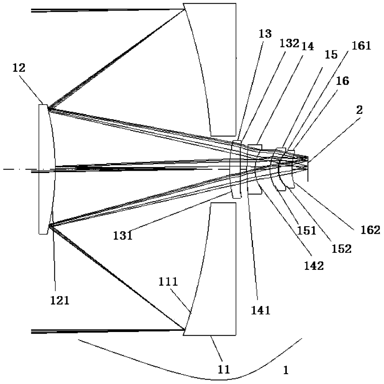
[0017] Such as figure 1 As shown, a star sensor optical imaging system for attitude determination of a deep-space exploration aircraft is coaxially arranged with a first reflector 1, a second reflector 2, a first positive meniscus lens 3, and a first negative curve The moon lens 4, the second negative meniscus lens 5, the second positive meniscus lens 6 and the detector 7, the incident light is reflected by the front surface 11 of the first reflector 1, and is incident on the rear surface 21 of the second reflector 2, and passes through it After reflection, it is incident on the first positive meniscus lens 3, and the incident light passes through the first positive meniscus lens 3, the first negative meniscus lens 4, the second negative meniscus lens 5 and the second positive meniscus lens 6, Finally received by detector 7.

[0018] The distance d1 between the front surface 11 of the first reflecting mirror 1 and the rear surface 21 of the second reflecting mirror 2 is 75mm<...


PUM


Abstract

The star sensor optical imaging system for attitude determination of deep space exploration aircraft belongs to the field of optical system technology. After being reflected, it enters the first positive meniscus lens, and the incident light passes through the first positive meniscus lens, the first negative meniscus lens, the second negative meniscus lens and the second positive meniscus lens in turn, and is finally detected by the detector Receiving; the distance between the front surface of the first mirror and the center of the back surface of the second mirror is d1, the distance between the back surface of the second mirror and the center of the front surface of the first positive meniscus lens is d2, and the distance between the back surface of the first positive meniscus lens and the center of the first positive meniscus lens The distance between the center of the front surface of a negative meniscus lens is d3, the distance between the back surface of the first negative meniscus lens and the center of the front surface of the second negative meniscus lens is d4, and the distance between the back surface of the second negative meniscus lens and the front surface of the second positive meniscus lens The distance between the center of the surface is d5, and the distance between the rear surface of the second positive meniscus lens and the center of the detector is d6.

Description

technical field [0001] The invention relates to a star sensor optical imaging system for attitude determination of a deep space exploration aircraft, which can be applied to the attitude determination of an outer space deep space exploration aircraft and belongs to the technical field of optical systems. Background technique [0002] There are various imaging types of star sensors according to the range of wavelengths used and the types of detectors. The structure of the star sensor that has been reported so far mostly adopts the transmissive type of the fully transmissive lens, the focal length of the system is generally 20mm-60mm, and the effective entrance pupil diameter is generally 10mm-50mm. This will lead to disadvantages such as low incident light energy received by the image detector per unit time, prolonged dynamic motion imaging integration time, slow image refresh rate, and slow speed of satellite attitude determination when observing targets such as faint small ...

Claims


Application Information

Patent Timeline
Patent Type & Authority Patents(China)
IPC IPC(8): G02B17/08G01C21/02
CPCG01C21/02G02B17/082
Inventor 吕博刘伟奇姜珊冯睿
Owner CHANGCHUN INST OF OPTICS FINE MECHANICS & PHYSICS CHINESE ACAD OF SCI
Why Eureka
Try Eureka