Optical Imaging Objective Lens for Lunar Edge with Spherical Ring and Large Field of View

An optical imaging, large field of view technology, applied in optics, optical components, installation, etc., can solve the problems of high detection cost of optical system parts and the whole machine, uncertain work stability, etc., to reduce procurement difficulty and reduce relative distortion. , the effect of reducing manufacturing costs

Active Publication Date: 2018-06-22
CHANGCHUN INST OF OPTICS FINE MECHANICS & PHYSICS CHINESE ACAD OF SCI
View PDF8 Cites 0 Cited by
  • Summary
  • Abstract
  • Description
  • Claims
  • Application Information

AI Technical Summary

Problems solved by technology

[0003] In order to solve the defects of high manufacturing and testing costs of optical system parts and complete machines in the prior art, and uncertain working stability in space environment, the present invention provides a spherical annular large field of view lunar edge optical imaging objective lens

Method used


Image

  • Optical Imaging Objective Lens for Lunar Edge with Spherical Ring and Large Field of View
  • Optical Imaging Objective Lens for Lunar Edge with Spherical Ring and Large Field of View
  • Optical Imaging Objective Lens for Lunar Edge with Spherical Ring and Large Field of View

Examples


Embodiment Construction

[0024] The present invention will be described in further detail below in conjunction with the accompanying drawings.

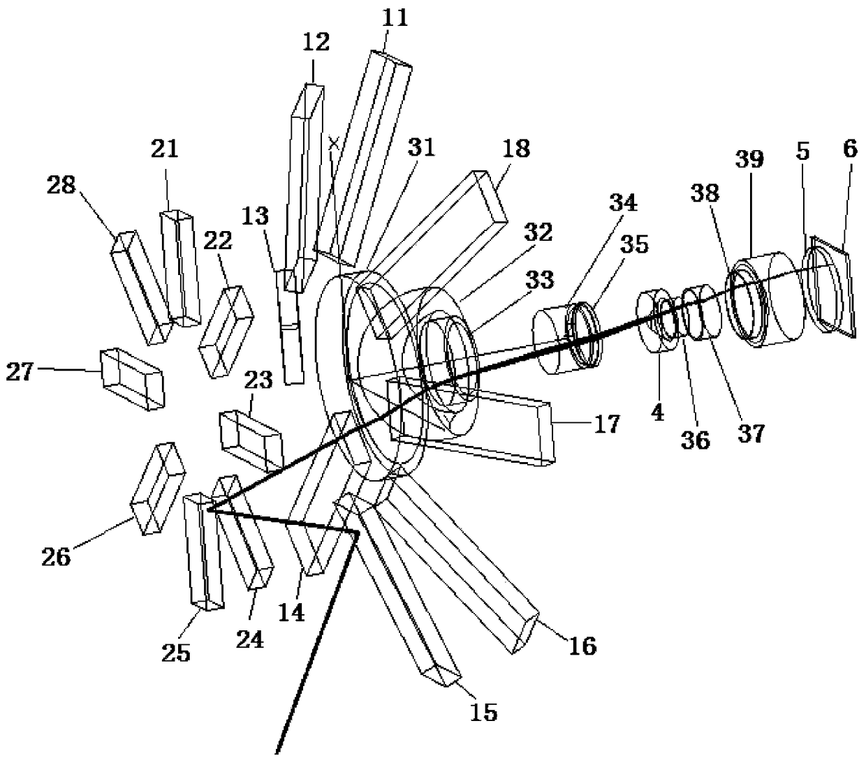
[0025] Such as figure 1 As shown, the optical imaging objective of the spherical annular large field of view on the edge of the moon is set coaxially according to the order of light incidence: the first plane mirror group 1, the second plane mirror group 2, the imaging lens group 3, the aperture 4, and the detector To protect the glass 5 and the detector 6 , the second plane mirror group 2 is located at the front end of the first plane mirror group 1 .

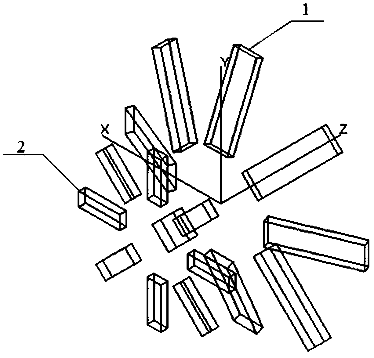
[0026] Such as figure 2 As shown, the first plane mirror group 1 includes a first plane mirror 11 uniformly distributed around the Z axis, a second plane mirror 12, a first plane mirror 13, a second plane mirror 14, and a second plane mirror 14. A plane mirror 15 , a second plane mirror 16 , a first plane mirror 17 and a second plane mirror 18 .

[0027] The second flat mirror group 2, which includes the ...


PUM


Abstract

The spherical annular large field of view lunar edge optical imaging objective lens belongs to the field of optical design technology. In order to solve the defects of high manufacturing and testing costs of optical system parts and complete machines in the prior art, and uncertain working stability in the space environment, according to the incident light The first plane mirror group, the second plane mirror group, the imaging mirror group, the diaphragm, the detector protection glass and the detector are coaxially arranged in sequence, the second plane mirror group is located at the front end of the first plane mirror group, and arranged in parallel; the first plane mirror group includes eight plane mirrors uniformly distributed around the Z-axis circumferential direction, the second plane mirror group includes eight plane mirrors uniformly distributed around the Z-axis circumferential direction, and two groups of plane mirrors There is one-to-one correspondence between the plane mirrors in the mirror group; the optical system is insensitive to the orbit height of the satellite around the moon, has high-resolution imaging, high imaging quality, and high pointing accuracy, and can adapt to the high-precision attitude determination of the spacecraft in the lunar reflection spectrum range, Reduce the attitude determination time of satellites flying around the moon.

Description

technical field [0001] The invention relates to a spherical annular large field of view lunar edge optical imaging objective lens, which belongs to the technical field of optical design. Background technique [0002] Satellites flying around the moon need to determine their own pitch and roll attitude in real time. The traditional attitude determination using the combination of star sensor and gyroscope requires the computer on the ground and the satellite to provide accurate orbit information. The accuracy of satellite attitude determination is very dependent on the accuracy of orbit determination, and the single attitude determination takes a long time. At the same time, when the star sensor on the near-orbit satellite around the moon images the moon, the optical system needs a field of view of 100° to 150° to cover the entire moon. For a single transmission imaging lens, small optical aberrations and high The pointing accuracy is relatively difficult in design and post-p...

Claims


Application Information

Patent Timeline
Patent Type & Authority Patents(China)
IPC IPC(8): G02B13/06G02B7/182G02B27/00
CPCG02B7/182G02B13/06G02B27/0012
Inventor 吕博姜珊冯睿张大亮魏忠伦付瀚毅刘伟奇
Owner CHANGCHUN INST OF OPTICS FINE MECHANICS & PHYSICS CHINESE ACAD OF SCI
Why Eureka
Try Eureka