Novel bus duct tapping device

A busway, a new type of technology, applied in the direction of open busway installation, riveting connection, etc., can solve the problem of reducing the contact resistance and temperature rise of the connection at the two ends of the busway and the plugging point of the branch line, the reduction of the rated operating current, Reduced safety protection performance and other issues, to achieve the effect of convenient and normal power supply, reliable contact, and high safety protection performance

Active Publication Date: 2016-04-06
JIANGSU HUAQIANG ELECTRIC EQUIP
View PDF5 Cites 7 Cited by
  • Summary
  • Abstract
  • Description
  • Claims
  • Application Information

AI Technical Summary

Problems solved by technology

[0002] With the emergence of modern engineering facilities and equipment, the power consumption of all walks of life is increasing rapidly, especially the emergence of many high-rise buildings and large workshops. The traditional cables used as power transmission wires can no longer meet the requirements in large current transmission systems. The parallel use of multi-channel cables has brought a lot of inconvenience to the on-site installation and construction connection. As a new type of power distribution wire, the plug-in busway has emerged. Its superiority, at the same time, due to the use of new technology and new technology, the contact resistance and temperature rise of the connection at the two ends of the bus duct and the connection of the branch port are greatly reduced, and high-quality insulation is used in the bus duct materials, thereby improving the safety and reliability of the bus duct, and making the whole system more perfect. However, the bus duct tap-off device in the prior art generally adopts the welding method, which leads to a decrease in rated operating current and a decrease in safety protection performance, and is not suitable for current connection. The subrack takes power normally

Method used


Image

  • Novel bus duct tapping device
  • Novel bus duct tapping device
  • Novel bus duct tapping device

Examples


Embodiment Construction

[0020] The embodiment of the substrate of the present invention will be further described below in conjunction with the accompanying drawings.

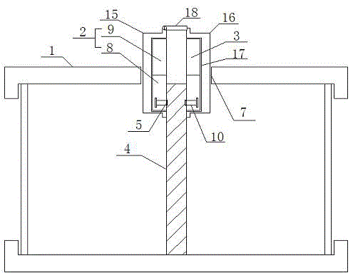
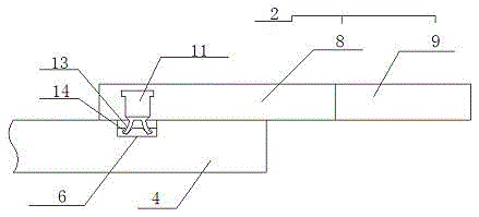
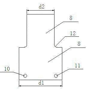
[0021] A new type of bus duct tapping device, comprising a bus duct housing 1, a first connecting copper bar 2 and a second connecting copper bar 3, wherein, the bus duct housing 1 is provided with a main bus bar 4, and the main bus bar 4 Both sides of the busbar 4 are respectively provided with a first installation groove 5 and a second installation groove 6, the busbar housing 1 is provided with an opening 7, the opening 7 is located on the side of the main busbar 4, the first connection Both the copper bar 2 and the second connecting copper bar 3 are composed of a primary plate 8 and a secondary plate 9, the primary plate 8 and the secondary plate 9 are rectangular structures, the width of the primary plate 8 is d1, The width of the secondary plate 9 is d2, the d1:d2=1.3:1;

[0022] One side of the primary plate 8 is connected to ...


PUM


Abstract

The invention relates to a novel bus duct tapping device, which comprises a bus duct shell, a first connecting copper bar and a second connecting copper bar, wherein a main busbar is arranged in the bus duct shell; a first mounting groove and a second mounting groove are formed in two sides of the main busbar respectively; each of the first connecting copper bar and the second connecting copper bar comprises a primary plate and a secondary plate; one side of the primary plate is connected with the secondary plate and the other side is provided with a first bolt and a second bolt; a first protective plate is arranged outside the first connecting copper bar; a second protective plate is arranged outside the second connecting copper bar; and a protective cover board is arranged between the first protective plate and the second protective plate. The novel bus duct tapping device does not need to weld; the rated working current is not reduced; the security protection performance is high; and normal power taking of a jack box of which the heavy current is greater than 630A can be facilitated.

Description

technical field [0001] The invention relates to a novel bus duct tapping device, which belongs to the technical field of electrical connectors. Background technique [0002] With the emergence of modern engineering facilities and equipment, the power consumption of all walks of life is increasing rapidly, especially the emergence of many high-rise buildings and large workshops. The traditional cables used as power transmission wires can no longer meet the requirements in large current transmission systems. The parallel use of multi-channel cables has brought a lot of inconvenience to the on-site installation and construction connection. As a new type of power distribution wire, the plug-in busway has emerged. Its superiority, at the same time, due to the use of new technology and new technology, the contact resistance and temperature rise of the connection at the two ends of the bus duct and the connection of the branch port are greatly reduced, and high-quality insulation i...

Claims


Application Information

Patent Timeline
Patent Type & Authority Applications(China)
IPC IPC(8): H02G5/02H01R4/06
CPCH01R4/06H02G5/02
Inventor 陈廷建
Owner JIANGSU HUAQIANG ELECTRIC EQUIP
Why Eureka
Try Eureka