Cryopump

A cryopump and cryopanel technology, which is applied to pumps, liquid variable displacement machines, machines/engines, etc., can solve problems such as unreasonable and increased regeneration time, and achieve the effects of suppressing increase, prolonging regeneration interval, and suppressing regeneration time

Active Publication Date: 2016-04-13
SUMITOMO HEAVY IND LTD
View PDF9 Cites 6 Cited by
  • Summary
  • Abstract
  • Description
  • Claims
  • Application Information

AI Technical Summary

Problems solved by technology

However, the inventors have found that this insight does not make sense at the later stages of the regeneration interval
In fact, at the later stage of the regeneration interval, if the aperture ratio is larger, it will actually promote the increase of the regeneration time.

Method used


Image

  • Cryopump
  • Cryopump
  • Cryopump

Examples


Embodiment Construction

[0020] Hereinafter, embodiments of the present invention will be described in detail with reference to the drawings. In addition, in the following description, the same code|symbol is attached|subjected to the same element, and repeated description is abbreviate|omitted suitably. In addition, the structures described below are examples and do not limit the scope of the present invention.

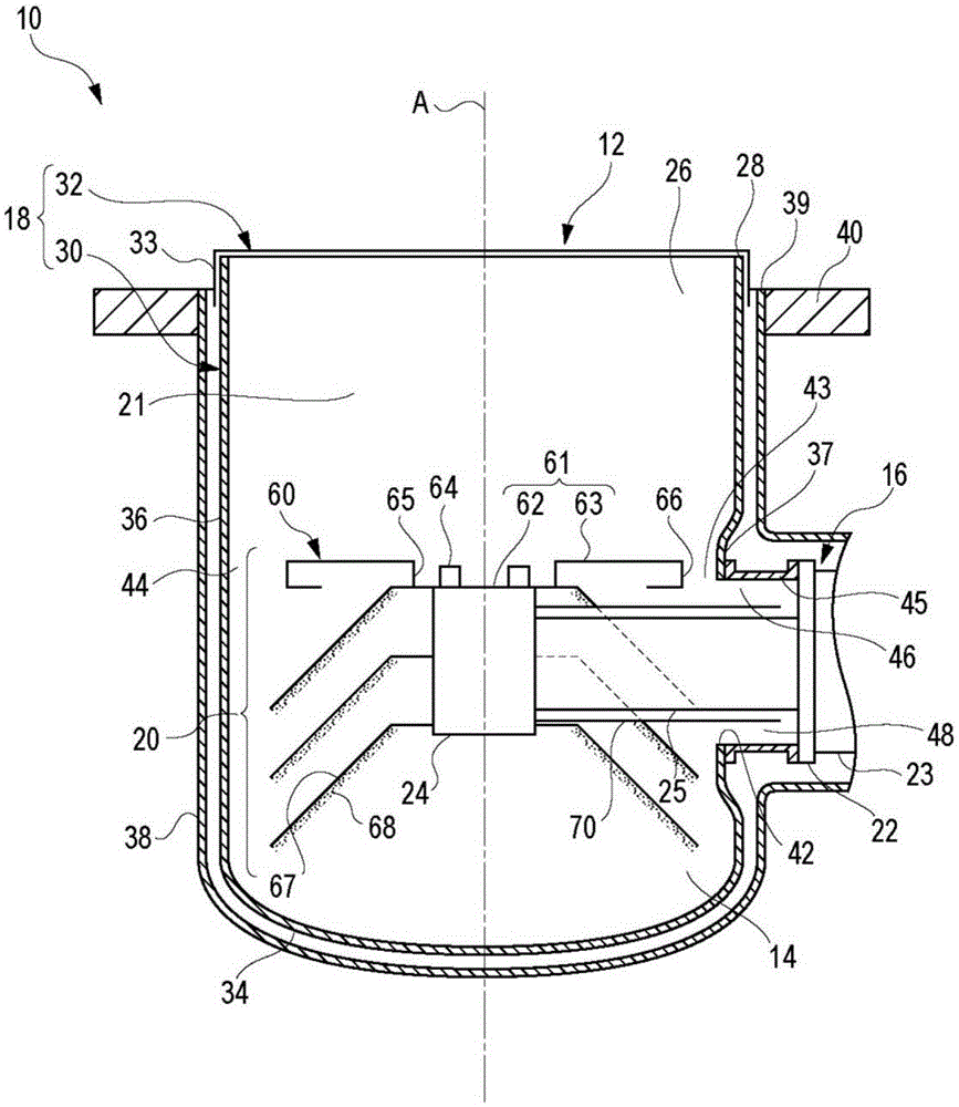
[0021] figure 1 It is a side cross-sectional view schematically showing main parts of a cryopump 10 according to an embodiment of the present invention. The cryopump 10 is installed, for example, in a vacuum chamber of a vacuum processing device, and is used to increase the degree of vacuum inside the vacuum chamber to a level required by a desired process. The vacuum processing apparatus equipped with the cryopump 10 is, for example, a sputtering apparatus. The process gas pressure in the sputtering device is, for example, in the range of 1 mTorr to 10 mTorr.

[0022] The cryopump 10 ha...


PUM


Abstract

A cryopump includes: a cryopump vessel that defines an inlet; a refrigerator including a first stage and a second stage housed in the cryopump vessel, the second stage being cooled to a lower temperature than that of the first stage; a first cryopanel thermally connected to the first stage and surrounded by the cryopump vessel; and a second cryopanel thermally connected to the second stage and surrounded by the first cryopanel. The first cryopanel includes a plate member having an inlet aperture at the inlet. The inlet aperture is formed in the plate member such that a ratio of a conductance of the plate member with respect to an aperture conductance of the inlet is 6% or less.

Description

[0001] This application claims priority based on Japanese Patent Application No. 2014-206158 filed on October 7, 2014. The entire contents of this Japanese application are incorporated herein by reference. technical field [0002] The invention relates to a cryopump. Background technique [0003] One of the uses of the cryopump is a vacuum processing device such as a sputtering device. In the vacuum processing apparatus, a vacuum process may be repeatedly performed. The main role of the cryopump in this device is to continuously maintain a vacuum suitable for the vacuum process. A cryopump is used to restore the vacuum to an appropriate level to allow the process to start during a temporary stand-by of the device between the previous process and the next process. The time required to restore the vacuum is called regeneration time. The shorter the regeneration time, the earlier the next process can be started, so the productivity of the device will increase. Therefore, i...

Claims


Application Information

Patent Timeline
Patent Type & Authority Applications(China)
IPC IPC(8): F04B37/08
CPCF04B37/085F04B37/08
Inventor 及川健
Owner SUMITOMO HEAVY IND LTD
Why Eureka
Try Eureka