
Pipe stabilizing and rotating device

A rotating device and a stable technology, which is applied in the field of pipe stabilization and rotating devices, can solve the problems of inconvenient clamping and rotation, and achieve fast and stable results

Active Publication Date: 2016-04-20
LUZHOU YUANCHENG ENG MACHINERY CO LTD
View PDF9 Cites 8 Cited by
  • Summary
  • Abstract
  • Description
  • Claims
  • Application Information

AI Technical Summary

Problems solved by technology

[0003] The purpose of the present invention is to provide a pipe stabilization and rotation device, which solves the problem of inconvenient clamping and rotation during pipe processing in the prior art, and realizes the purpose of conveniently and quickly stabilizing and rotating the pipe to be processed at the same time

Method used


Image

  • Pipe stabilizing and rotating device
  • Pipe stabilizing and rotating device
  • Pipe stabilizing and rotating device

Examples


Embodiment 1

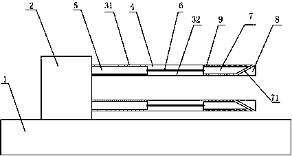
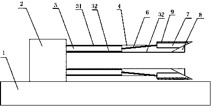
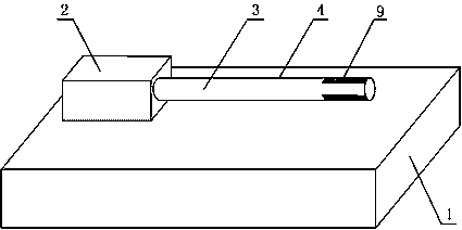
[0016] Such as Figure 1 to Figure 3 The shown pipe stabilization and rotation device includes a base 1 and a motor 2 arranged on the base 1. A hollow main shaft 3 is connected to the rotating shaft of the motor 2. The main shaft 3 includes an outer cylinder 31 and an inner cylinder 32. , an annular gap 4 is formed between the outer cylinder 31 and the inner cylinder 32, and an electric push rod 5, a connecting rod 6, a slider 7, and a stopper 8 are arranged in the annular gap 4, and the two ends of the connecting rod 6 Respectively hinged with the electric push rod 5 and the slider 7, the stopper 8 is fixed at the end of the annular gap 4, and the surface of the stopper 8 is gradually extending from the inner cylinder 32 to the outer cylinder 31 along the extension direction of the main shaft 3. The outer inclined curved surface, the sliding surface 71 of the slider 7 matches the surface of the stopper 8; the outer cylinder 31 is provided with a window for the slider 7 to sli...

Embodiment 2

[0018] Such as Figure 1 to Figure 3 In the shown pipe stabilization and rotation device, on the basis of Embodiment 1, multiple groups of electric push rods 5, connecting rods 6, sliders 7, and stoppers are arranged in the annular gap 4. 8. A single slider 7 has limited frictional resistance provided by its slips 9, and has limited stability for the pipe to be processed. Therefore, multiple sets of sliders 7 are pushed to move simultaneously through multiple sets of electric push rods 5 controlled simultaneously. And increase the frictional force of the pipe to be processed through more slips 9, improve the stabilization effect, and ensure that it can rotate under the drive of the main shaft.


PUM


Abstract

The invention discloses a pipe stabilizing and rotating device. The pipe stabilizing and rotating device comprises a base, and a motor arranged on the base; a rotating shaft of the motor is connected with a hollow main shaft; the main shaft includes an outer cylinder and an inner cylinder; an annular gap is formed between the outer cylinder and the inner cylinder; an electric push rod, a connecting rod, a slide block and a stopper are arranged in the annular gap; the two ends of the connecting rod are respectively hinged with the electric push rod and the slide block; the stopper is fixed at the end part of the annular gap; the surface of the stopper is a curved surface gradually inclined outwards from the inner cylinder to the outer cylinder in the main shaft extending direction; and the slide surface of the slide block is matched with the surface of the stopper. The invention aims to provide the pipe stabilizing and rotating device, solves the problem of inconvenience for clamping and rotation in the pipe processing process in the prior art, and realizes the purpose of conveniently and quickly stabilizing a pipe to be processed while rotating.

Description

technical field [0001] The invention relates to the field of pipe clamping devices, in particular to a pipe stabilization and rotation device. Background technique [0002] The clamping device is a commonly used device in various mechanical processing processes. It is used to fix the materials or parts to be processed to ensure that they will not move and deviate during the processing, and to avoid the deviation of the items to be processed from affecting the operation. For cylindrical pipes, it is easy to roll during production, processing and cutting, and it is necessary to fix them before subsequent work. The existing pipe fixing devices usually use chains or pipe wrench for fixing, but when the pipe needs to be stretched or a large force is applied, it is easy to cause the phenomenon of pipe detachment, displacement, etc., and the pipe cannot be fixed stably and reliably, and the pipe Jumping will occur during the rotation, which will affect the cutting, grinding and ot...

Claims


Application Information

Patent Timeline
Patent Type & Authority Applications(China)
IPC IPC(8): B23B31/40B23Q7/00B25B11/00B24B41/06
CPCB23B31/404B23B2215/72B23Q7/00B24B41/06B25B11/00
Inventor 马赟
Owner LUZHOU YUANCHENG ENG MACHINERY CO LTD
Learn More