Rubber node, power bogie and rail vehicle

A technology for power bogies and rubber joints, which is applied to bogies, railway car body parts, shock absorbers, etc., and can solve the problems that the stiffness of rubber joints cannot adapt to changes in the vibration frequency of rail vehicles

Active Publication Date: 2016-04-20
CRRC TANGSHAN CO LTD
View PDF7 Cites 30 Cited by
  • Summary
  • Abstract
  • Description
  • Claims
  • Application Information

AI Technical Summary

Problems solved by technology

[0005] The invention provides a rubber node, a power bogie and a rail vehicle to solve the problem in the prior art that the stiffness of the rubber node cannot adapt to the change of the vibration frequency of the rail vehicle during operation

Method used


Image

  • Rubber node, power bogie and rail vehicle
  • Rubber node, power bogie and rail vehicle
  • Rubber node, power bogie and rail vehicle

Examples


Embodiment 1

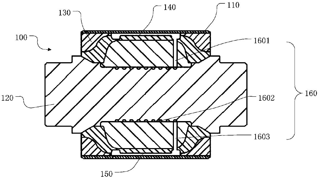
[0042] figure 1 A cross-sectional view of a rubber joint. Such as figure 1 As shown, the rubber node 100 provided by the present invention is used to connect the axle box and the frame to provide stability for the movement of the bogie, which includes: a casing 110 , a mandrel 120 and a rubber layer 130 . The mandrel 120 is located in the casing 110, and a rubber layer 130 is filled between the mandrel 120 and the casing 110, and an upper cavity 140 and a lower cavity are opened on the rubber layer 130 on both sides of the symmetrical upper and lower sides of the mandrel 120, respectively. 150. Meanwhile, a first communication channel 160 is also provided between the upper cavity 140 and the lower cavity 150 . Liquid is injected in the upper cavity 140 and the lower cavity 150, and the filled liquid does not fill the whole upper cavity 140 and the lower cavity 150, that is, after filling the liquid, the upper cavity 140 and the lower cavity The liquid in the cavity 150 can...

Embodiment 2

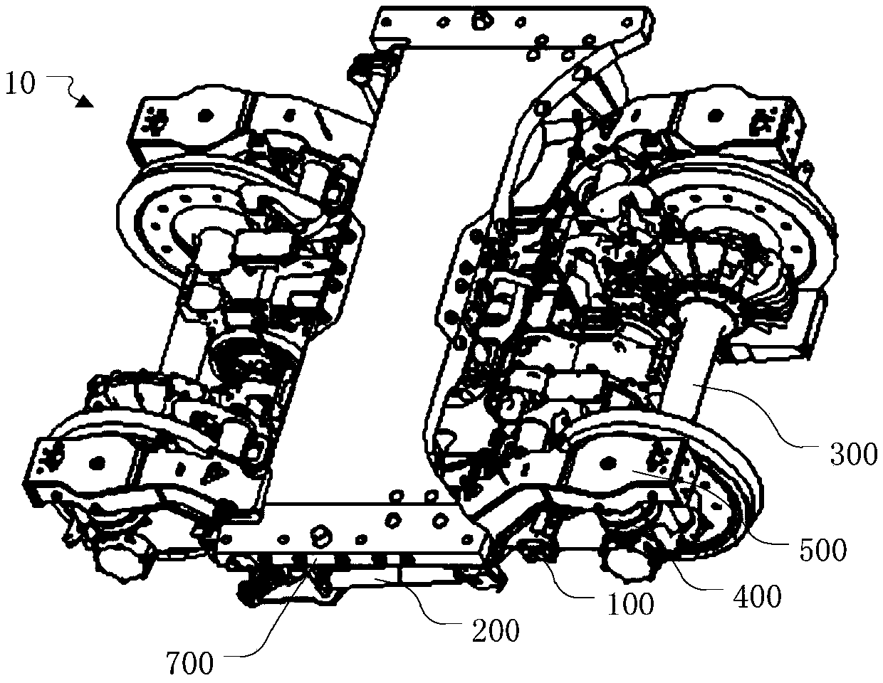
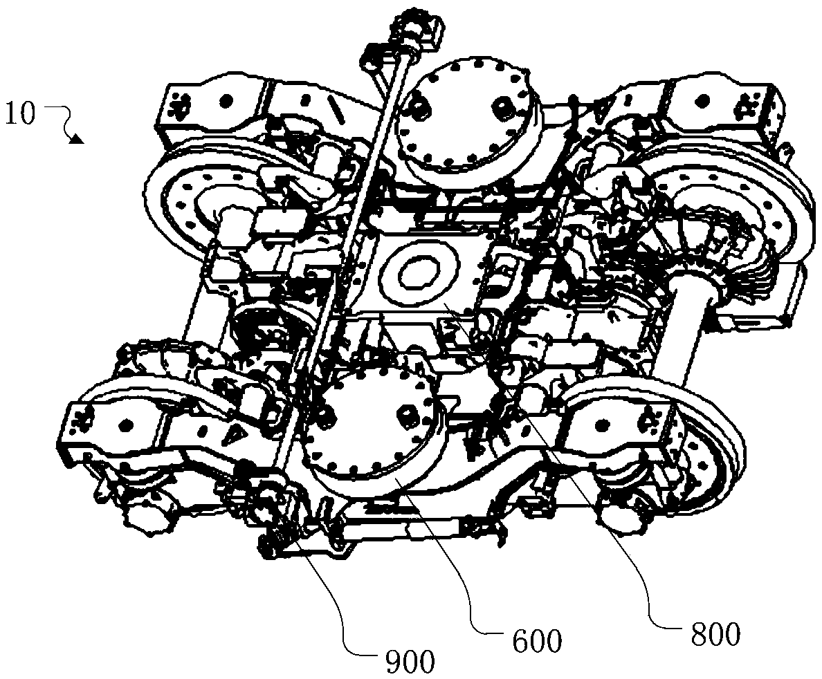
[0049] figure 2 Schematic diagram of the structure of the power bogie, image 3 for figure 2 Schematic diagram of the structure after removing the bolster. Such as figure 2 with image 3 As shown, the power bogie 10 of the present invention includes: rubber nodes 100, anti-serpentine shock absorbers 200, wheel sets 300, axle boxes, coil spring groups 400, frame 500, air springs 600, bolsters 700, central traction 800, anti-roll torsion bar 900 and disc foundation brake. Axleboxes are installed at both ends of the wheel set 300, a coil spring set 400 is installed above the axlebox, a frame 500 is installed above the coil spring set 400, and the rubber node 100 described in Embodiment 1 is installed between the axlebox and the frame 500. An air spring 600 is installed in the lower recess of the frame 500 , a bolster 700 is installed above the air spring 600 , and a central traction 800 that transmits the traction force of the motor is installed between the two air spring...

Embodiment 3

[0057] The third aspect of the present invention provides a rail vehicle, on which the rubber node 100 described in Embodiment 1 is installed, or on which the power bogie 10 described in Embodiment 2 is installed.

[0058] In the rail vehicle of this embodiment, an upper cavity 140 and a lower cavity 150 communicated through a first communicating channel 160 are opened on the rubber layer 130 on the upper and lower sides of the rubber node 100 symmetrical with respect to the mandrel 120, and the upper cavity 140 Liquid is injected into the lower cavity 140 and the lower cavity 150, and the liquid does not fill the entire upper cavity 140 and the lower cavity 150. When the rail vehicle vibrates at low frequencies, fluid can freely flow quickly between the upper cavity 140 and the lower cavity 150, thereby providing a standard stiffness for the rail vehicle. When the vibration frequency of the rail vehicle gradually increases, the liquid cannot flow rapidly between the upper cav...


PUM


Abstract

The invention provides a rubber node, a power bogie, and a rail vehicle; the rubber node comprises a mandrel, a sheath, and a rubber layer filled between the mandrel and the sheath; a first cavity and a second cavity are symmetrically arranged on two sides of the rubber layer around the mandrel, and connected through a first connecting channel; the first and second cavities are filled with liquid, yet not fully filled; the rubber node is connected between an axle box and a truss of the power bogie; the rail vehicle comprises the rubber node; the first and second cavities are symmetrically arranged on two side of the rubber layer round the mandrel, connected through the first connecting channel, and filled with liquid, so the rigidity of the rubber node can change with liquid flow resistances, thus adapting to rail vehicle vibration frequency.

Description

technical field [0001] The invention relates to a rubber node, a power bogie and a rail vehicle, and belongs to the technical field of rail vehicle manufacturing. Background technique [0002] The rubber joint is an important connecting element between the axle box arm and the frame of the rail vehicle. It is widely used in subways, light rail and other urban rail vehicles and high-speed trains. The rubber joint is responsible for transmitting the longitudinal force of traction or braking, ensuring the stable operation of the train and It has important functions such as good guiding ability. [0003] The existing rubber joint is installed between the frame and the axle box rotating arm, which includes a mandrel, a jacket, and a rubber layer filled between the mandrel and the jacket. [0004] The rigidity of the existing rubber nodes is invariable, and the rigidity cannot be adjusted as the frequency changes during the operation of the rail vehicle, so that the running stabi...

Claims


Application Information

Patent Timeline
Patent Type & Authority Applications(China)
IPC IPC(8): B61F5/30F16F13/18
CPCB61F5/305F16F13/18
Inventor 卢权张隶新郭继祥张冠兰王家鑫
Owner CRRC TANGSHAN CO LTD
Why Eureka
Try Eureka