Rubber nodes, power bogies and rail vehicles
A rubber node and rubber layer technology, which is applied to bogies, railway car body parts, shock absorbers, etc., can solve the problem that the stiffness of rubber nodes cannot adapt to changes in the vibration frequency of rail vehicles
- Summary
- Abstract
- Description
- Claims
- Application Information
AI Technical Summary
Problems solved by technology
Method used
Image
Examples
Embodiment 1
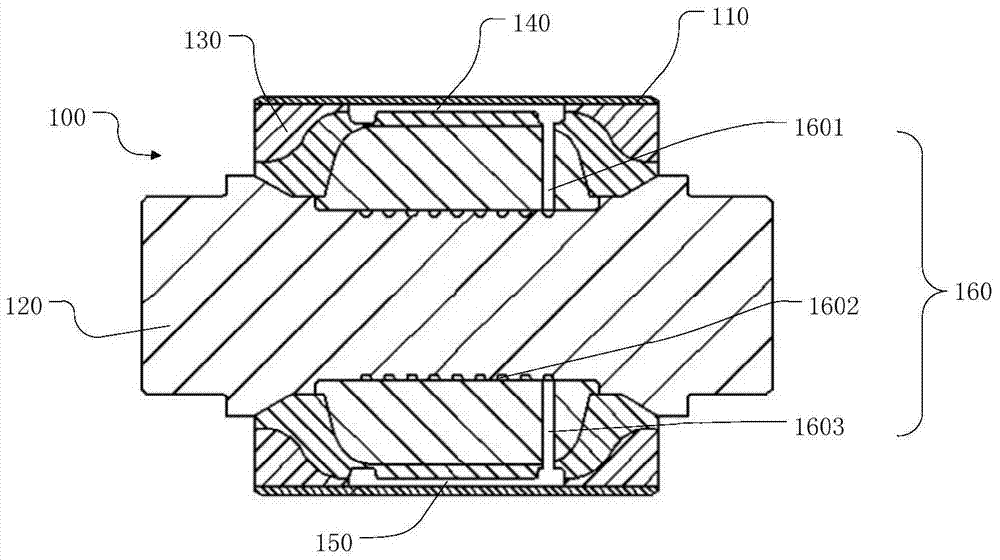
[0042] figure 1 A cross-sectional view of a rubber joint. like figure 1 As shown, the rubber node 100 provided by the present invention is used to connect the axle box and the frame to provide stability for the movement of the bogie, which includes: a casing 110 , a mandrel 120 and a rubber layer 130 . The mandrel 120 is located in the casing 110, and a rubber layer 130 is filled between the mandrel 120 and the casing 110, and an upper cavity 140 and a lower cavity are opened on the rubber layer 130 on both sides of the symmetrical upper and lower sides of the mandrel 120, respectively. 150. Meanwhile, a first communication channel 160 is also provided between the upper cavity 140 and the lower cavity 150 . Liquid is injected in the upper cavity 140 and the lower cavity 150, and the filled liquid does not fill the whole upper cavity 140 and the lower cavity 150, that is, after filling the liquid, the upper cavity 140 and the lower cavity The liquid in the cavity 150 can fr...
Embodiment 2
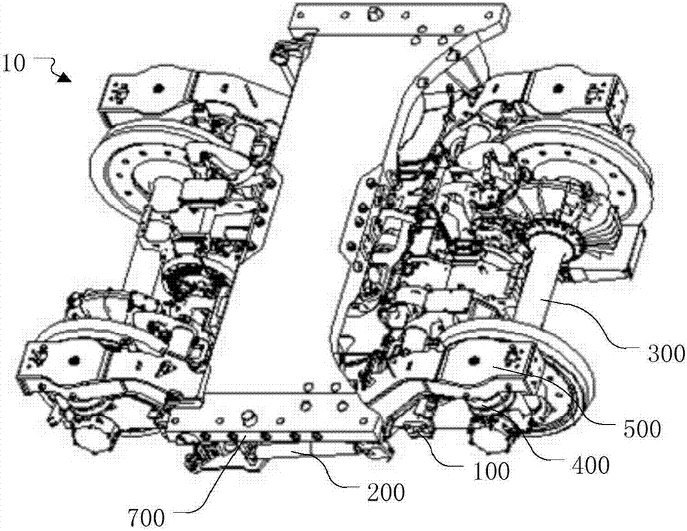
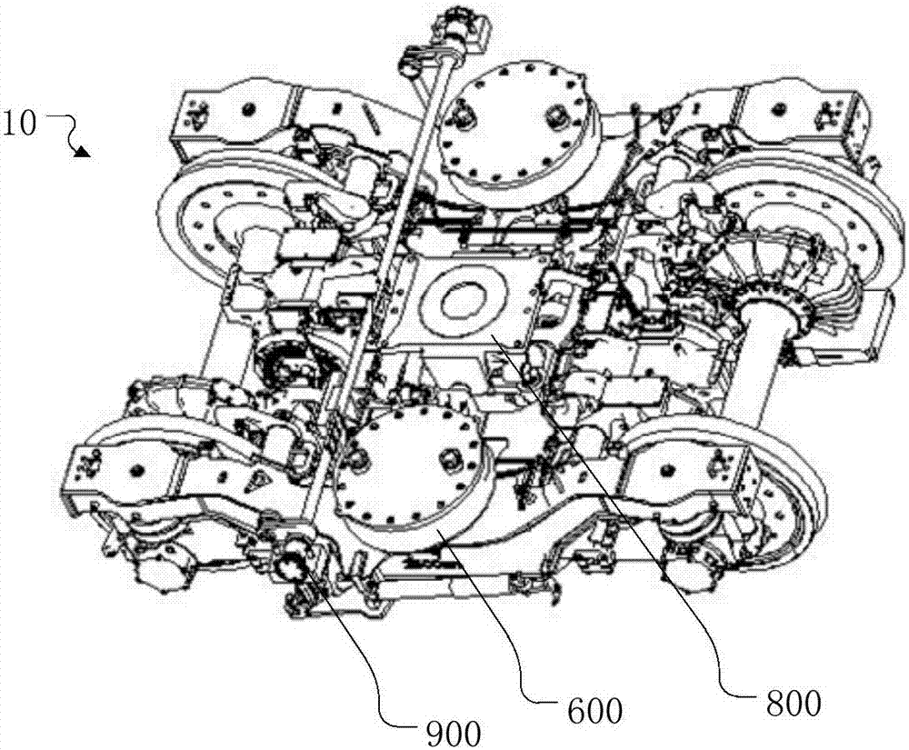
[0049] figure 2 Schematic diagram of the structure of the power bogie, image 3 for figure 2 Schematic diagram of the structure after removing the bolster. like figure 2 and image 3 As shown, the power bogie 10 of the present invention includes: rubber nodes 100, anti-serpentine shock absorbers 200, wheel sets 300, axle boxes, coil spring groups 400, frame 500, air springs 600, bolsters 700, central traction 800, anti-roll torsion bar 900 and disc foundation brake. Axleboxes are installed at both ends of the wheel set 300, a coil spring set 400 is installed above the axlebox, a frame 500 is installed above the coil spring set 400, and the rubber node 100 described in Embodiment 1 is installed between the axlebox and the frame 500. An air spring 600 is installed in the lower recess of the frame 500 , a bolster 700 is installed above the air spring 600 , and a central traction 800 that transmits the traction force of the motor is installed between the two air springs 60...
Embodiment 3
[0057] The third aspect of the present invention provides a rail vehicle, on which the rubber node 100 described in Embodiment 1 is installed, or on which the power bogie 10 described in Embodiment 2 is installed.
[0058] In the rail vehicle of this embodiment, an upper cavity 140 and a lower cavity 150 communicated through a first communicating channel 160 are opened on the rubber layer 130 on the upper and lower sides of the rubber node 100 symmetrical with respect to the mandrel 120, and the upper cavity 140 Liquid is injected into the lower cavity 140 and the lower cavity 150, and the liquid does not fill the entire upper cavity 140 and the lower cavity 150. When the rail vehicle vibrates at low frequencies, fluid can freely flow quickly between the upper cavity 140 and the lower cavity 150, thereby providing a standard stiffness for the rail vehicle. When the vibration frequency of the rail vehicle gradually increases, the liquid cannot flow rapidly between the upper cav...
PUM
 Abstract
Description
Claims
Application Information
 - R&D
- Intellectual Property
- Life Sciences
- Materials
- Tech Scout
- Unparalleled Data Quality
- Higher Quality Content
- 60% Fewer Hallucinations
Browse by: Latest US Patents, China's latest patents, Technical Efficacy Thesaurus, Application Domain, Technology Topic, Popular Technical Reports.
© 2025 PatSnap. All rights reserved.Legal|Privacy policy|Modern Slavery Act Transparency Statement|Sitemap|About US| Contact US: help@patsnap.com


