Electronic cabinet lock and control method thereof

A technology of electronic and cabinet locks, which is applied in the field of electronic locks, can solve problems such as unsatisfactory locks, and achieve the effects of simple and reliable structure, meeting technical requirements, and high promotion value

Active Publication Date: 2016-04-20
WUHAN PULINGUANGTONG TECH
View PDF6 Cites 25 Cited by
  • Summary
  • Abstract
  • Description
  • Claims
  • Application Information

AI Technical Summary

Problems solved by technology

[0003] In order to overcome the above-mentioned deficiencies, the purpose of the present invention is to provide an electronic cabinet lock and its control method to the art, so that it can solve the above-mentioned technical problems that cannot be satisfied in the existing locksets

Method used


Image

  • Electronic cabinet lock and control method thereof
  • Electronic cabinet lock and control method thereof
  • Electronic cabinet lock and control method thereof

Examples


Embodiment 1

[0036] Embodiment 1: An electronic cabinet lock.

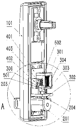
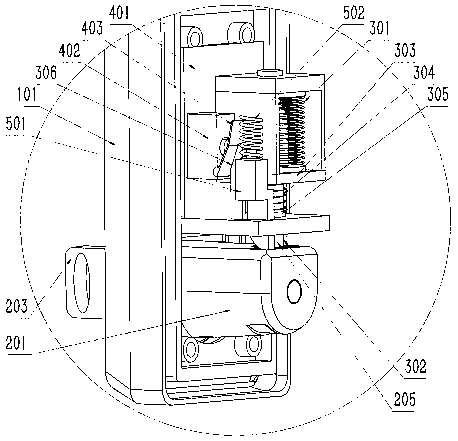
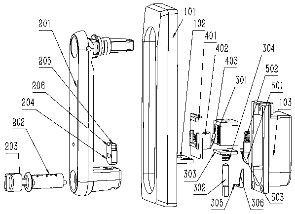
[0037] Such as figure 1 As shown, it is a schematic diagram of the explosion structure of the electronic cabinet lock; figure 2 As shown, it is a schematic diagram of the internal structure of the electronic cabinet lock when it is locked; image 3 shown, for figure 2 The enlarged schematic diagram of part A in ; Figure 4As shown, it is a schematic diagram of the internal cross-sectional structure of the electronic cabinet lock when it is locked; it can be seen in the figure that the electronic cabinet lock is composed of a lock body base and a handle that is movably connected to the lock body base at the upper end; the lower end of the handle is A mechanical lock cylinder is installed in the lock hole, and the mechanical lock cylinder can be rotated and unlocked under the control of the mechanical key. The rear end of the mechanical lock cylinder is connected with a card plate that can move up / down; card slot. There i...

Embodiment 2

[0051] Embodiment two: a kind of electronic cabinet lock control method, comprising:

[0052] A1. In the initial state, the electromagnetic coil is kept reversely energized, and the electromagnetic coil, the first permanent magnet and the second structure jointly maintain a downward force on the bearing, the bearing remains extended, and the lower end of the bearing falls into the slot of the clamping plate , and interlock with the deck on the top of the deck, the control handle is closed in the base of the lock body, and the electronic cabinet lock is in the closed state;

[0053] A2. When automatic unlocking is required, the electromagnetic coil of the self-holding electromagnet is energized in the forward direction, and the magnetic attraction force generated by the electromagnetic coil on the bearing or the second structure on the bearing makes the bearing move upward, and the bearing and the clamp are out of the buckled state , the handle is detached from the base of the ...

Embodiment 3

[0058] Embodiment 3: A method for controlling an electronic cabinet lock. The difference between this embodiment and Embodiment 2 is that the electronic cabinet lock includes a reset tongue and a reset spring; the control method includes:

[0059] B1. In the initial state, the electromagnetic coil is kept reversely energized, the electromagnetic coil, the first permanent magnet and the second structure jointly maintain a downward force on the bearing, the bearing keeps extending, and the lower end of the bearing falls into the slot of the clamping plate , and interlock with the card table on the top of the card plate, the control handle is closed in the base of the lock body, and the electronic cabinet lock is in the closed state; the lower end of the reset tongue falls on the outer wall of the handle or the card plate, and the return spring is compressed;

[0060] B2. When automatic unlocking is required, the electromagnetic coil of the self-holding electromagnet is energized...


PUM


Abstract

The invention provides an electronic cabinet lock and a control method thereof. The electronic cabinet lock is simple in structure, and the control method is clear in principle. By a self-retaining electromagnet capable of keeping a bearing state feature after power failure and by mutual fastening of a bearing and a clamping plate, a function of automatic daily unlocking of an electronic lock is realized while a function that only the lock in fault can be unlocked by a key is achieved, technical market requirements on the electronic lock can be met, and high promotion value is achieved.

Description

Technical field [0001] The present invention involves electronic locks, which specifically involves an electronic cabinet lock and its control method. Background technique [0002] With the vigorous development of information technology, outdoor cabinets are gradually replacing traditional equipment rooms due to the small space, easy installation, unified specifications, and high protection performance.EssenceAnd traditional outdoor cabinets often only install mechanical cabinet locks, which cannot meet the requirements of access control management after informationization; China Tower Group currently proposes a new cabinet access control solution.If the access control system fails, such as power failure, network interruption, equipment failure, etc., the problem of opening the door through mechanical keys to avoid the risk of mechanical keys to be easily copied and difficult to manage.The traditional electronic cabinet lock, due to the constraints of the structure of the lock, s...

Claims


Application Information

Patent Timeline
Patent Type & Authority Applications(China)
IPC IPC(8): E05B65/52E05B47/02E05B3/00
CPCE05B3/00E05B47/0006E05B47/02E05B65/52E05B2047/0091E05B47/0657E05B1/0092E05B5/003E05B13/10E05B47/0004E05B2047/0085E05B47/0005E05B2047/0094
Inventor 徐志国李佳汪精武
Owner WUHAN PULINGUANGTONG TECH
Why Eureka
Try Eureka