Rotary device with combined drive shaft and combined drive shaft

A technology for rotating devices and transmission shafts, which is applied in the direction of transmission devices, transmission device parts, gear transmission devices, etc., to achieve the effect of improving transmission efficiency and reducing backlash

Active Publication Date: 2018-02-27
IND TECH RES INST
View PDF4 Cites 0 Cited by
  • Summary
  • Abstract
  • Description
  • Claims
  • Application Information

AI Technical Summary

Problems solved by technology

[0004] The present invention is to provide a rotating device with a combined transmission shaft and the combined transmission shaft, so as to solve the problem of backlash between the cam and the roller
These driven rollers are set around the turret

Method used


Image

  • Rotary device with combined drive shaft and combined drive shaft
  • Rotary device with combined drive shaft and combined drive shaft
  • Rotary device with combined drive shaft and combined drive shaft

Examples


Embodiment Construction

[0047] The technical solution of the present invention will be described in detail below in conjunction with the accompanying drawings and specific embodiments to further understand the purpose, solution and effect of the present invention, but it is not intended to limit the scope of protection of the appended claims of the present invention.

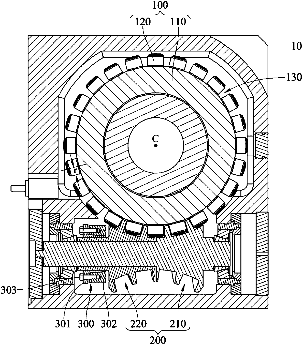
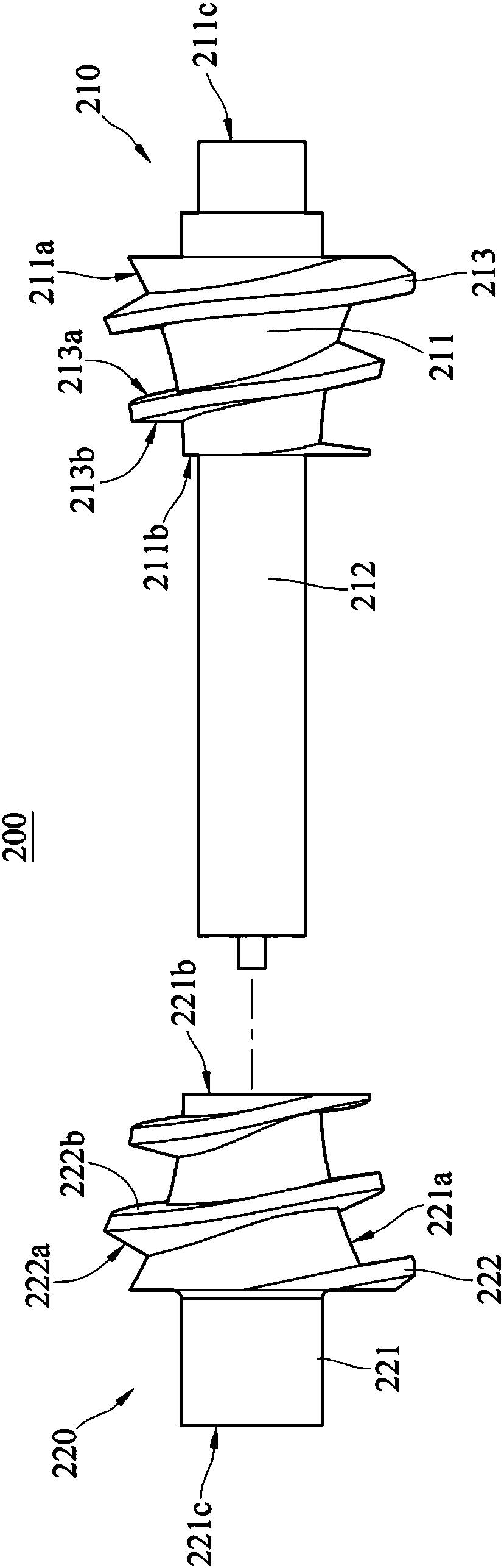
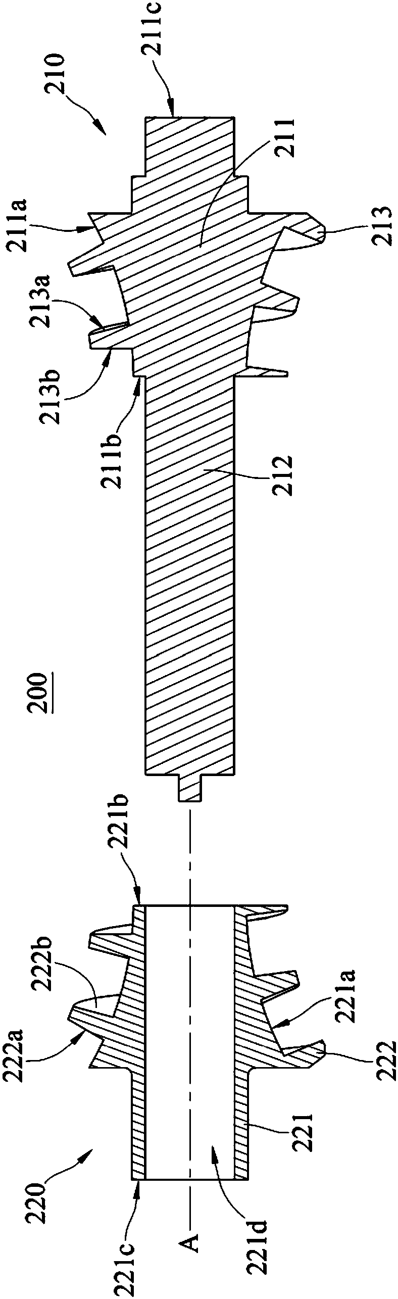
[0048] see Figure 1 to Figure 4 . figure 1 It is a schematic cross-sectional view of the rotating device of the first embodiment. figure 2 for figure 1 The exploded side view schematic diagram of the combined drive shaft. image 3 for figure 1 The exploded cross-sectional schematic diagram of the combined transmission shaft. Figure 4 for figure 1 The cross-sectional schematic diagram of the combination of the combined transmission shaft.

[0049] Such as figure 1 As shown, the rotating device 10 with the combined transmission shaft 200 in this embodiment includes a rotating disk 100 , a combined transmission shaft 200 and a c...


PUM


Abstract

The invention discloses a rotating device with a combined transmission shaft, which includes a rotating disk and a combined transmission shaft. The rotating disc includes a turret and a plurality of driven rollers. The combined transmission shaft includes a first hobbing cam and a second hobbing cam. The first hobbing cam includes a first shaft part, an assembly shaft part and a first helical tooth part. The assembly shaft protrudes from one side of the first shaft. The first helical tooth portion helically surrounds the first shaft portion and has a first outer surface and a first inner surface opposite to each other. The second hobbing cam includes a second shaft portion and a second helical tooth portion. The second shaft part has an assembly shaft hole. The second helical tooth helically surrounds the second shaft portion and has a second outer surface and a second inner surface opposite to each other. The second inner surface faces the first inner surface. The assembling shaft portion of the first hobbing cam passes through the assembling shaft hole of the second hobbing cam. The invention solves the problems of lower transmission efficiency and shortened cam life caused by the backlash between the rotating disc and the combined transmission shaft.

Description

technical field [0001] The invention relates to a rotating device, in particular to a rotating device with a combined transmission shaft and the combined transmission shaft. Background technique [0002] The follower (Follower) of a cam mechanism such as a roller gear cam and a parallel index cam is a turret (Turret). A number of rollers are fixed around the turret, arranged radially and at equal intervals. When the cam rotates, the roller is regulated and pushed by the groove of the cam, which makes the turret rotate. [0003] When the cam mechanism is running at high speed, it is easy to generate negative torque due to the large inertia load. At this time, if there is a backlash between the cam and the roller, knocking will occur and vibration will occur, which will not only reduce the transmission efficiency, but also shorten the life of the cam. Therefore, various manufacturers all want to solve the backlash problem. Contents of the invention [0004] The present i...

Claims


Application Information

Patent Timeline
Patent Type & Authority Patents(China)
IPC IPC(8): F16H37/12
CPCF16H57/12F16H1/166F16H55/24F16H2057/125F16H2057/127
Inventor 吴庆辉戴添喜谢章嘉吴明章蔡圣丰吴明儒
Owner IND TECH RES INST
Why Eureka
Try Eureka