Display screen structure and driving method thereof

A technology of display screen and sub-pixel, applied in the field of display screen, can solve the problems of increased power consumption of display screen, increase of manufacturing cost of driving unit, reduction of Y-axis, etc., and achieve the effect of saving power consumption and improving the problem of shortening lifespan

Pending Publication Date: 2021-02-02
FUJIAN HUAJIACAI CO LTD
View PDF0 Cites 0 Cited by
  • Summary
  • Abstract
  • Description
  • Claims
  • Application Information

AI Technical Summary

Problems solved by technology

The existing display screen is a source line (Source Line) of IC (integrated chip, also used as a drive unit) corresponding to a data line (Data Line) in the plane, and one data line of the display screen controls a sub-pixel, resulting in The number of source traces is too large, so that the Y axis of the IC cannot be reduced, which increases the power consumption of the display screen and increases the production cost of the driving unit.

Method used


Image

  • Display screen structure and driving method thereof
  • Display screen structure and driving method thereof
  • Display screen structure and driving method thereof

Examples


Embodiment 1

[0044] Please refer to Figure 1 to Figure 4 , Embodiment 1 of the present invention is:

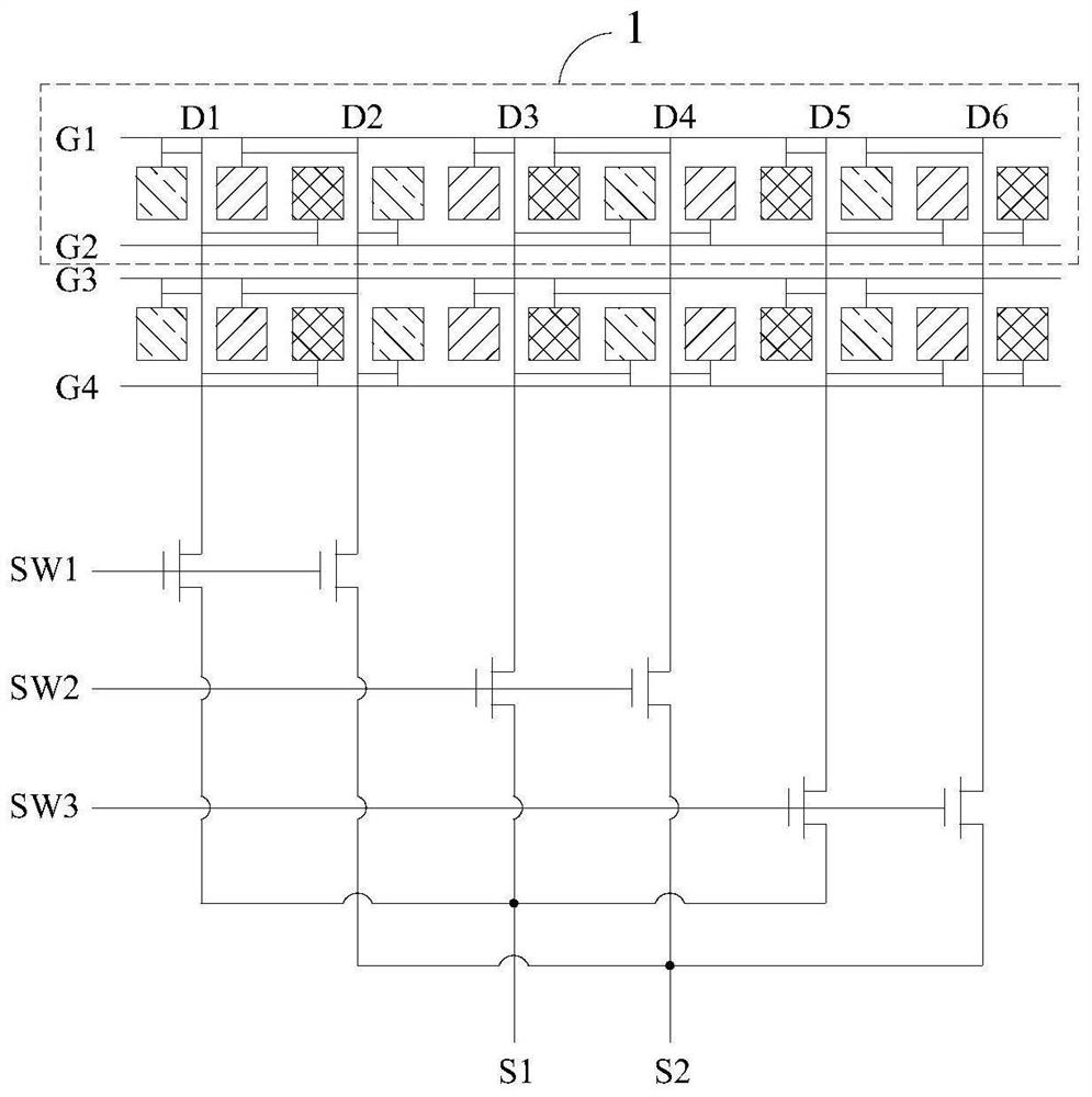
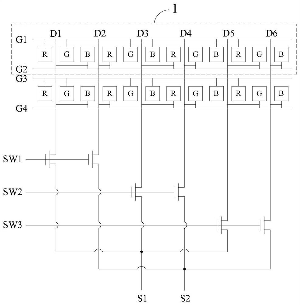
[0045] Please refer to figure 1 and figure 2 , a display structure, including more than two pixel units 1, a first Demux wiring (Demux wiring is also called decompositing unit structure wiring), a second Demux wiring, a third Demux wiring and a plurality of gates Pole wires, one pixel unit 1 is configured with two gate wires and is located between the two gate wires;

[0046] Please refer to figure 1 and figure 2 , each of the pixel units 1 includes six columns of sub-pixel pairs arranged in sequence from left to right, the sub-pixel pairs in the first column and the sub-pixel pairs in the second column are divided into the first sub-pixel group, and the sub-pixel pairs in the third column are divided into sub-pixel groups. The sub-pixel pair in the column and the sub-pixel pair in the fourth column are divided into the second sub-pixel group, and the sub-pixel pair in the fifth c...

Embodiment 2

[0057] Please refer to Figure 5 , the second embodiment of the present invention is:

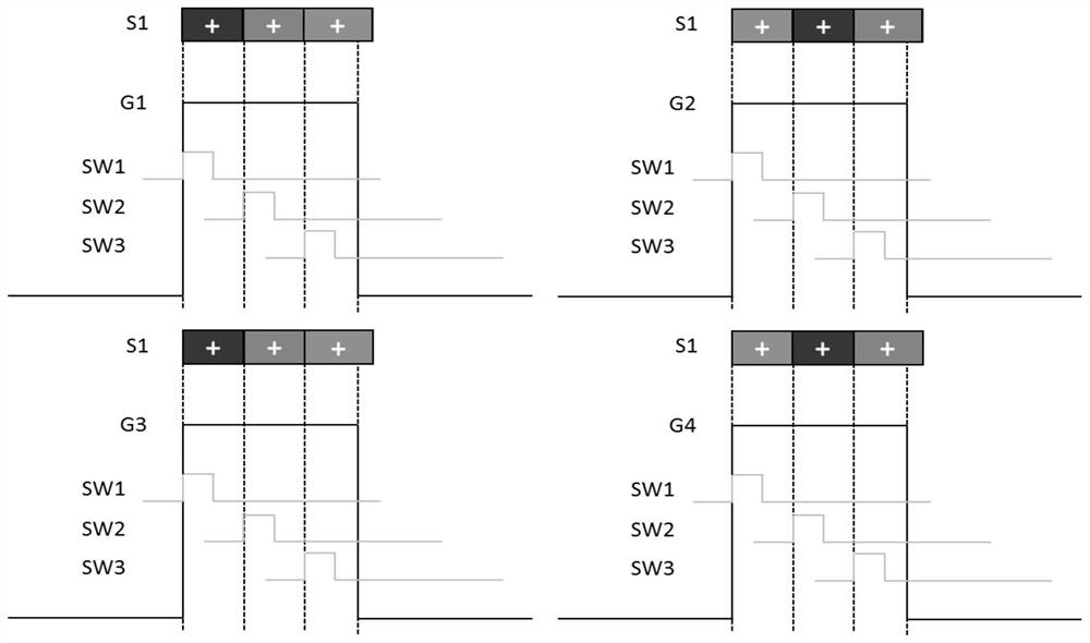
[0058] A method for driving a display screen structure, comprising the following steps:

[0059] Step S1, in one pixel unit 1, controlling one of the two gate lines to be turned on;

[0060] Step S2, during the opening period of a gate line, sequentially control the opening of the first Demux line, the second Demux line and the third Demux line; during the opening period of the first Demux line, control the source line to transmit the signal To the pixel pair connected to the data traces at the first and second locations; during the turn-on of the second Demux trace, the control source trace transmits the signal to the data trace connections at the third and fourth locations during the turn-on period of the third Demux wiring, control the source wiring to transmit the signal to the pixel pair connected to the data wiring at the fifth position to the sixth position;

[0061] Step S3, cont...


PUM


Abstract

The invention relates to the technical field of display screens, in particular to a display screen structure and a driving method thereof. The display screen structure comprises two or more pixel units, a first Demux wire, a second Demux wire, a third Demux wire and a plurality of gate wires, and one pixel unit is provided with two gate wires and located between the two gate wires; grid electrodesof all TFT switches in the first sub-pixel group are electrically connected with the first Demux wire, grid electrodes of all TFT switches in the second sub-pixel group are electrically connected with the second Demux wire, grid electrodes of all TFT switches in the third sub-pixel group are electrically connected with the third Demux wire, and the input terminal of each TFT switch is correspondingly connected with one source wire. In this way, the number of the source electrode wires of the IC is reduced to 1 / 6 of that of a common panel, due to the fact that the number of the source electrode wires of the IC is reduced, the IC becomes narrower on the Y axis, and the full-screen effect of the display screen can be achieved.

Description

technical field [0001] The invention relates to the technical field of display screens, in particular to a display screen structure and a driving method thereof. Background technique [0002] Frame and full-screen display designs have become the mainstream. With the widespread popularity of displays, the screen-to-body ratio of the first-generation iPhone in 2007 was only about 50%. In the following years, the screen-to-body ratio of mobile phones will It continues to improve, but not by much. In existing display screens, the Y-axis length of the driving unit is an important factor affecting a full screen or a narrow bezel screen. The existing display screen is a source line (Source Line) of IC (integrated chip, also used as a drive unit) corresponding to a data line (Data Line) in the plane, and one data line of the display screen controls a sub-pixel, resulting in Too many source wires prevent the Y axis of the IC from being reduced, which increases the power consumption...

Claims


Application Information

Patent Timeline
Patent Type & Authority Applications(China)
IPC IPC(8): G09F9/30G09F9/302G09G3/20
CPCG09F9/30G09F9/302G09G3/20G09G2310/0267
Inventor 谢建峰熊克
Owner FUJIAN HUAJIACAI CO LTD
Why Eureka
Try Eureka