


Quick Research
Generate reliable direction feasibility study reports for your R&D in just a few steps.

Technical Q&A
Discover and master advanced knowledge NOW. Basics, ideas, possibilities, all at once.

Find Solutions
As an expert in R&D theories, this can generate solutions to your technical problems instantly.

Evaluate Feasibility
Analyze your overall solution with one click, know your potential R&D risks in advance.

Monitor Landscape
Get weekly tech updates, stay abreast of the latest tech innovations and key insights.
Current sensor arrangement
A current sensor and inductor technology, applied in the direction of inductors, fixed inductors, and only current measurement, can solve the problem that Rogowski coils cannot be used with multi-phase conductor systems, and achieve the effect of reducing the effect
- Summary
- Abstract
- Description
- Claims
- Application Information
AI Technical Summary
Problems solved by technology
Method used
Image

Examples
Embodiment approach
[0100] According to an implementation manner, the short circuit detection device can also realize identification of a short circuit to ground. By properly designing the detection means, any current value can be defined as a signal threshold for the short circuit identification. In this way, even low short-circuit currents, such as 10 to 20 times the rated current of the drive or motor, can be detected and a corresponding auxiliary short-circuit generated. In this way, existing short-circuit devices that are generally classified as having reached a critical point of performance (especially at low short-circuit currents) can still perform fully (in the case of rated short-circuit).
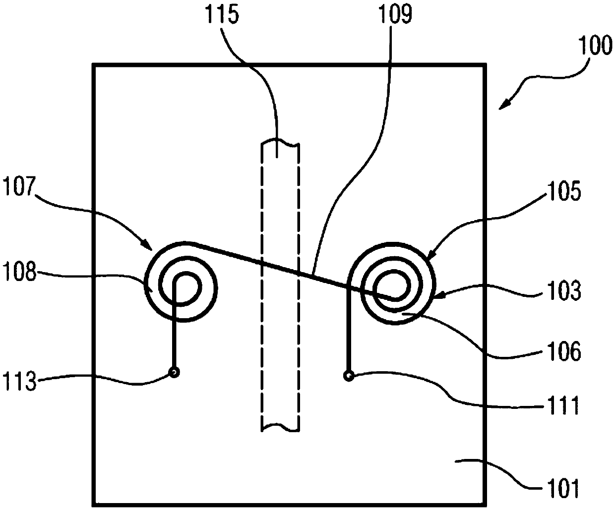
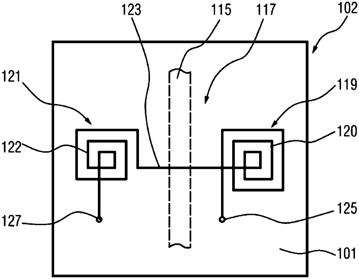
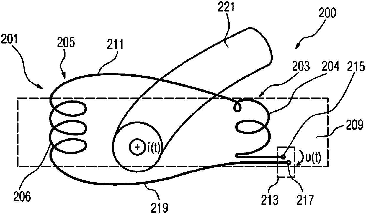
[0101] According to an embodiment, the measuring device, eg the current sensor arrangement, may be used to measure short-circuit currents in a three-phase power system.
[0102] According to one embodiment, a Rogowski coil can be used as the basis for the current measurement and can be a compressed...
PUM
 Abstract
Description
Claims
Application Information
 - R&D Engineer
- R&D Manager
- IP Professional
- Industry Leading Data Capabilities
- Powerful AI technology
- Patent DNA Extraction
Browse by: Latest US Patents, China's latest patents, Technical Efficacy Thesaurus, Application Domain, Technology Topic, Popular Technical Reports.
© 2024 PatSnap. All rights reserved.Legal|Privacy policy|Modern Slavery Act Transparency Statement|Sitemap|About US| Contact US: help@patsnap.com