
Lifting mechanism for blinds

A lifting mechanism and shutter technology, applied in the field of doors and windows, can solve the problems of rope loops scratching or overlapping, the lifting mechanism is stuck, and the spacing is difficult to guarantee, and achieves the effects of tight and orderly arrangement, convenient assembly, and stable transmission.

Active Publication Date: 2017-10-24
广东寰宇汉狮建材科技有限公司
View PDF1 Cites 0 Cited by
  • Summary
  • Abstract
  • Description
  • Claims
  • Application Information

AI Technical Summary

Problems solved by technology

[0003] However, when the lifting mechanism with the above structure is adopted, when the lifting rope is wound on the transmission rod, it is difficult to ensure the distance between the loops wound on the transmission rod, and the loops are more likely to scratch or overlap, which is easy Cause the shutter blades to jump during the lifting process. In serious cases, it may even cause the lifting mechanism to be stuck

Method used


Image

  • Lifting mechanism for blinds
  • Lifting mechanism for blinds
  • Lifting mechanism for blinds

Examples


Embodiment 1

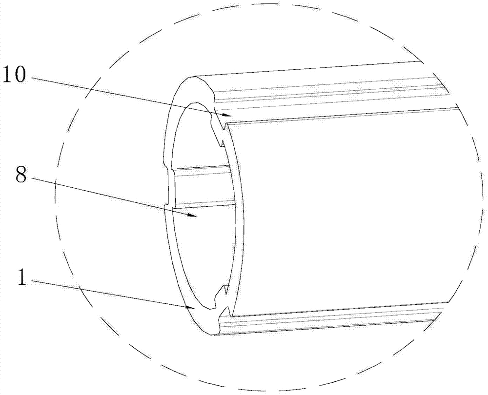
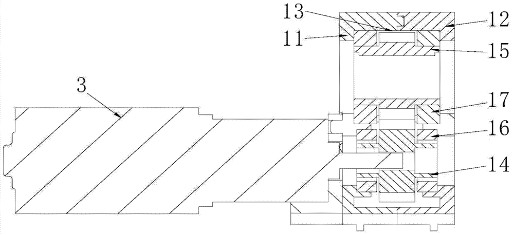
[0034] like figure 1 , 2 The lifting mechanism shown includes a transmission rod 1, a screw rod 2, a motor 3, a gear transmission block 4, a bearing seat 5, two dialing rope seats 6 and a travel switch 7. The transmission rod 1 is a hollow structure, and the transmission rod 1 is provided with transmission rod through holes 8 distributed along its longitudinal direction. The transmission rod through hole 8 runs through the entire transmission rod 1 longitudinally along the transmission rod 1, so that the screw rod 2 extends into the transmission rod 1, and at the same time reduces the weight of the transmission rod 1, so that the power mechanism drives the transmission rod 1 to rotate. One end of the transmission rod 1 is connected with the gear transmission block 4, and the gear transmission block 4 is connected with the motor 3; One end of the screw rod 2 extends into the through hole 8 of the transmission rod, and the other end is fixed on the receiving seat 5 . The tran...

Embodiment 2

[0045] The difference between this embodiment 2 and embodiment 1 is that in this embodiment 2, if Figure 9-11 As shown, a turning wheel 28 is also provided in the dialing rope seat 6, and a turning wheel fastening block 29 is provided in the turning wheel 28, and the turning wheel fastening block 29 is embedded in the fastening groove 10, so that the turning wheel 28 can follow the transmission Rod 1 turns to turn. The turning wheel 28 is provided with a turning pull cord 31 for adjusting the angle of the louver blade, and the turning pull cord 31 is connected with the louver leaf. The connection method between the overturning pull cord 31 and the louver leaf can refer to the existing louver, and will not be repeated here.

[0046] When the louver leaf needs to be turned over, the operator starts the motor 3, and the motor 3 drives the second gear 15 to rotate through the first gear 14, and then drives the transmission rod 1 to rotate a small angle, and the louver leaf can b...


PUM


Abstract

The invention discloses a lifting mechanism for shutters. Particularly, the lifting mechanism comprises a threaded rod and a transmission rod which can rotate automatically relative to the threaded rod. The transmission rod is provided with a power mechanism used for driving the transmission rod to rotate and further provided with a nut which is fixed relative to the transmission rod, and the nut is engaged with the threaded rod. The transmission rod is further provided with a plurality of rope fixing wheels which are fixed relative to the transmission rod, and the rope fixing wheels are provided with lifting pull ropes for enabling shutter leaves to go up and down. The lifting mechanism for the shutters is simple in structure, convenient to assemble and smooth and steady in transmission; a threaded transmission mechanism and a gear transmission mechanism are adopted, rope rings wound on the transmission rod are made to be arranged compactly and orderly, and the lifting action of the shutter blades is smooth and steady.

Description

technical field [0001] The invention relates to the technical field of doors and windows, in particular to a lifting mechanism for blinds. Background technique [0002] At present, the existing blind lifting mechanism generally adopts a connection structure between a pulley and a transmission rod. The rotation of the transmission rod drives the pulley to rotate, and then drives the lifting rope installed on the pulley to wind on the transmission rod to realize the lifting of the louvers. For example, the patent document with the authorized announcement number CN 203614004 U discloses a flip-up and lift mechanism for blinds. , a sliding device arranged in the side frame, a lifting rope connecting the corner connection device and the sliding device, a flipping dimming rope, and a limit base fixed at the bottom of the side frame. [0003] However, when the lifting mechanism with the above structure is adopted, when the lifting rope is wound on the transmission rod, it is diffi...

Claims


Application Information

Patent Timeline
Patent Type & Authority Patents(China)
IPC IPC(8): E06B9/32E06B9/326
CPCE06B9/32E06B9/326
Inventor 杨程辉
Owner 广东寰宇汉狮建材科技有限公司
Learn More