
Vehicle-mounted emergency rescue lighting device and control method thereof

A control method and technology for lighting devices, which are applied to lighting devices, lighting auxiliary devices, portable lighting devices, etc., can solve the problems of difficulty in realizing large-angle rotation, limited rotation angle of lighting lamps, and limited lighting range, and achieve strong adaptability, The effect of facilitating rescue operations and improving equipment performance and service life

Active Publication Date: 2018-07-13
河南宜和城保装备科技实业有限公司
View PDF8 Cites 1 Cited by
  • Summary
  • Abstract
  • Description
  • Claims
  • Application Information

AI Technical Summary

Problems solved by technology

For example, the applicant applied for the emergency lighting vehicle with the patent number 200920089447.5 on April 7, 2009 and the 02270469.8 multifunctional emergency power supply vehicle applied for on October 29, 2002, and the announcement number published on April 2, 2014 is CN 203517565 U's patent name is vehicle-mounted mobile lighting equipment. The defects of these traditional vehicle-mounted lighting equipment are: 1) the rotation angle of the lighting lamp is limited, and it is difficult to achieve a large-angle rotation of more than 360 degrees; 2) usually two lighting lamps can only Synchronous pitching and rotation, and the lighting range is limited, it is impossible to realize that the two lights can rotate in different directions and illuminate in two different directions; 3) The lifting mechanism adopts a wire rope pulley mechanism, which has poor stability and is prone to slipping or entanglement of the wire rope situation, even after long-term use, there is a safety hazard of wire rope breakage

Method used


Image

  • Vehicle-mounted emergency rescue lighting device and control method thereof
  • Vehicle-mounted emergency rescue lighting device and control method thereof
  • Vehicle-mounted emergency rescue lighting device and control method thereof

Examples


Embodiment Construction

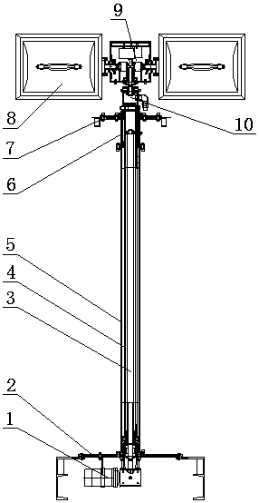
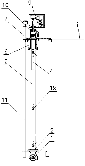
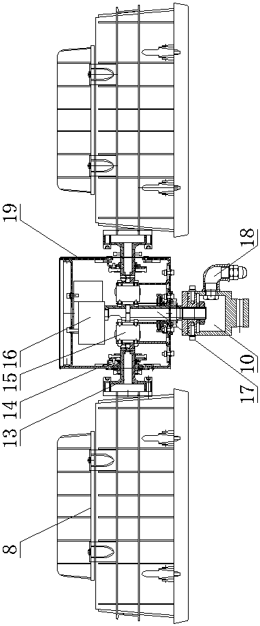
[0038] Such as Figure 1-5 Shown: a vehicle-mounted emergency rescue lighting device, including a control system, a lifting mechanism, a rotating and pitching assembly 9 and two lighting lamps 8, the lifting mechanism includes a lead screw 3 and a sleeve 4 threaded therewith, and a casing The outer sleeve 5 outside the sleeve 4, the outer sleeve 5 can be a round tube, square tube or other polygonal pipe fittings, the outer sleeve 5 and the lead screw 3 are fixed on the carriage or the crossbeam by the fixing bracket 2, and the lower end of the lead screw 3 is connected There is a lifting motor 1, the top of the outer sleeve 5 is provided with a guide cylinder 6, the lower end of the guide cylinder 6 is fixedly connected with the outer sleeve 5, the guide sleeve 6 is provided with a sliding sleeve on the sleeve 4, and the upper end of the guide cylinder 6 passes through The fixed frame is connected with the box body 11 of the carriage, and a waterproof cover plate 7 is arranged...


PUM


Abstract

The invention discloses a vehicle-mounted emergency rescue lighting device and a control method thereof. The lighting device includes a control system, a lifting mechanism, a rotating and pitching assembly and at least two lighting lamps. The lifting mechanism includes a lead screw and a sleeve threaded therewith Tube, the rotating and pitching assembly includes a plurality of pitching motors connected to the lighting lamps through the pitching shaft, and a rotating motor connected to the left and right rotating shafts, and the pitching shaft and the left and right rotating shafts are respectively provided with multi-level limit assemblies. The device has powerful functions and strong adaptability. It can not only meet the needs of the same direction of irradiation, but also meet the needs of different directions of irradiation. The lifting action is more stable and reliable, and it has a self-locking function. The large-angle rotation and positioning ensure the demand for large-angle rotating lighting in the emergency rescue process, which is convenient for emergency operations; the control method uses the limit sensor of the lifting mechanism to ensure the safe operation of the device and realizes automatic reset.

Description

technical field [0001] The invention belongs to the technical field of vehicle-mounted lighting devices, and in particular relates to a vehicle-mounted emergency rescue lighting device and a control method thereof. Background technique [0002] With the rapid development of my country's economy and urbanization, industries such as electric power, communication, transportation, fire protection, municipal administration, water supply, and gas supply have also developed rapidly, followed by emergency rescue work for various accidents. Increase, especially in places where there is a lack of lighting conditions for emergency rescue at night in the wild, providing all-round emergency lighting equipment can greatly improve the efficiency of emergency rescue, minimize the losses caused by various safety accidents, and avoid catastrophic accidents. [0003] Under the demand of the market, various emergency lighting vehicles have emerged, which integrate vehicle transportation, lightin...

Claims


Application Information

Patent Timeline
Patent Type & Authority Patents(China)
IPC IPC(8): F21L2/00F21V21/14F21V23/00F21V23/04H05B37/02
Inventor 孙四军李志军任德超
Owner 河南宜和城保装备科技实业有限公司
Learn More