
Rapid-assembling and dissembling split clamp used for fatigue test

A fatigue test, split-type technology, applied in the direction of measuring devices, analysis materials, instruments, etc., can solve the problems of poor clamping accuracy and consistency, affect test accuracy, inconsistent design load, etc., achieve high clamping and disassembly efficiency, improve The effect of test accuracy, convenience and fast accuracy

Active Publication Date: 2016-04-27
BEIHANG UNIV +1
View PDF18 Cites 9 Cited by
  • Summary
  • Abstract
  • Description
  • Claims
  • Application Information

AI Technical Summary

Problems solved by technology

However, in the actual test process, due to the errors in the processing and clamping of the test piece, additional loads may be generated during the test process, resulting in the inconsistency between the actual load of the test piece and the design load, thus affecting the test accuracy
At present, most of the fatigue test fixtures are single-piece design, which are fixed on the fatigue testing machine through threads or pressure plates. When there is a clamping error on the specimen, adaptive compensation cannot be performed, and the centering error caused by manual clamping cannot be eliminated.
At the same time, when threaded connection is used, the alignment inspection needs to be re-tested every time the test is disassembled, which takes a long time, and the clamping accuracy and consistency are poor, which directly limits the test progress and affects the test accuracy.

Method used


Image

  • Rapid-assembling and dissembling split clamp used for fatigue test
  • Rapid-assembling and dissembling split clamp used for fatigue test
  • Rapid-assembling and dissembling split clamp used for fatigue test

Examples


Embodiment Construction

[0024] In conjunction with the accompanying drawings, the operating mode of the present invention for the specimen fatigue life test fixture is further described:

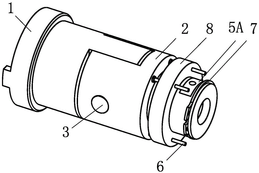
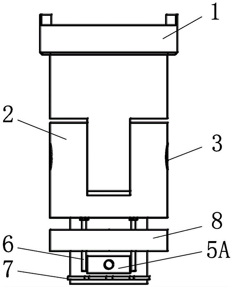
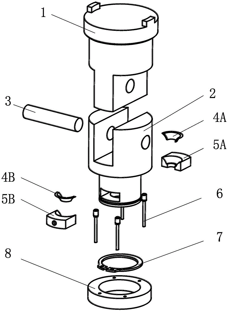
[0025] Step 1: use the pin shaft 3 to connect the upper clamp body 1 and the lower clamp body 2; screw the guide rod 6 into the threaded hole at the lower part of the lower clamp body 2 to complete the installation of the guide rod; install the collar 8 into the lower clamp body 2 Lower part; put the retaining ring 7 into the groove at the lower part of the lower clamp body 2; use glue to paste the left gasket 4A on the left support plate 5A, and paste the right gasket 4B on the right support plate 5B; push the collar 8, Expose the radial hole at the lower part of the lower clamp body 8, and insert the left and right gaskets into the radial hole from both sides. Complete the installation of the clamp body assembly.

[0026] Step 2: Install the upper and lower clamp components on the beam and base of the fatigue te...


PUM


Abstract

The invention relates to a rapid-assembling and dissembling split clamp used for fatigue test, and belongs to the field of material performance test. The split clamp is used for testing the tensile fatigue life of a metal material. Fatigue life test of a component or material is needed to improve the reliability of a part and enhance the safety of a machine device. In the practical test process, inconsistence of the practical bearing load and the design load of the test piece, caused by errors existing in the test piece processing and clamping process and extra load possibly generated in the test process, has influences on the test precision. The test piece fatigue life test clamp is provided to solve the above problem, adopts split design, has centering self-adaptability, and can effectively solve the centering error in the clamping process; and when test piece is replaced, dismounting of a clamp body is not needed, the test piece clamping is fast, the centering precision is consistent, the workload of centering detection is reduced, and the test process is accelerated.

Description

technical field [0001] The invention relates to a quick loading and unloading split fixture for fatigue testing, which is used for testing the tensile fatigue life of metal materials and belongs to the field of material performance testing. Background technique [0002] In modern mechanical equipment, fatigue fracture is the main reason for the damage and failure of mechanical parts and engineering components. Therefore, in order to improve the reliability of parts and enhance the safety of mechanical equipment, it is necessary to conduct fatigue life tests on parts or materials in advance. [0003] With the development of metal material fatigue test technology, a complete set of test technical specifications for tensile fatigue test has been formed at home and abroad. Due to the large load force during the fatigue test of metal materials, in order to accurately control the test load and improve the test accuracy, the relevant technical specifications have strict requiremen...

Claims


Application Information

Patent Timeline
Patent Type & Authority Applications(China)
IPC IPC(8): G01N3/04
CPCG01N3/04
Inventor 陈志同罗扬卢廷钧陈其南赵越蒋理科应少军
Owner BEIHANG UNIV
Learn More