C-arm lifting control device

A lift control and C-arm technology, which is applied in the field of C-arm lift control devices, can solve the problems of angle control that cannot be lifted by the C-arm, operator damage, reduced safety, etc., and achieves good performance and stability. Good, smooth and smooth lifting process

Active Publication Date: 2018-06-19
浙江红松影像科技有限公司
View PDF5 Cites 0 Cited by
  • Summary
  • Abstract
  • Description
  • Claims
  • Application Information

AI Technical Summary

Problems solved by technology

Because medical devices such as X-ray machines have radiation during use, adjusting them during operation will cause certain damage to the operator, resulting in poor performance and reduced safety
At the same time, manual operation cannot accurately control the angle of C-arm lifting

Method used


Image

  • C-arm lifting control device
  • C-arm lifting control device

Examples


Embodiment 1

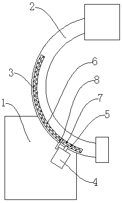
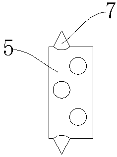
[0016] Such as figure 1 , figure 2 As shown, the lifting control device of the C-arm described in this embodiment includes a base 1 and a C-arm 2 slidably mounted on the base 1, and an arc-shaped track 3 is arranged on the C-arm 2. The bending direction of the arc-shaped track 3 is consistent with the bending direction of the C-shaped arm 2; at least one row of concave holes 6 is arranged on the arc-shaped track 3 in the arc direction, and the intervals between the concave holes 6 on the same row are uniform On the base 1, the motor 4 is fixed, the output shaft of the motor 4 is provided with a driving wheel 5, and at least one row of convex cones 7 is arranged on the circumference of the driving wheel 5, and the convex cone 7 is arranged on the circumference of the driving wheel 5 The number of rows of 7 is consistent with the number of rows of concave holes 6 on the arc track 3, and any row of concave holes 6 on the arc track 3 corresponds to one row of convex cones 7 on t...


PUM


Abstract

The invention relates to the field of medical instrument and equipment, in particular to a lift control device for a C-shaped arm. The lift control device comprises a base and the C-shaped arm slidably installed on the base, the C-shaped arm is provided with an arc-shaped rail, the arc-shaped rail is provided with at least one row of inwards-concaved holes in the arc direction, and the inwards-concaved holes formed in the same row are uniformly spaced; an electromotor is fixed on the base, an output shaft of the electromotor is provided with a drive wheel, at least one row of convex cones are arranged on the circumference of the drive wheel, the row number of the convex cones arranged on the circumference of the drive wheel is consistent with the row number of the inwards-concaved holes formed in the arc-shaped rail, and any one row of the inwards-concaved holes formed in the arc-shaped rail correspond to one row of the convex cones arranged on the drive wheel. According to the lift control device for the C-shaped arm, rotation of the C-shaped arm is achieved through cooperation of the inwards-concaved holes formed in the arc-shaped rail and the convex cones arranged on the drive wheel, and the usability is better; meanwhile, through the design of multiple rows of the inwards-concaved holes and the convex cones, the lift process is steadier and smoother, the positioning precision is high, and the stability is good.

Description

technical field [0001] The invention relates to the field of medical equipment, in particular to a lifting control device for a C-arm. Background technique [0002] At present, many medical devices, such as X-ray machines, use C-arm lifting, and use the C-arm to connect the equipment at both ends for control and operation. However, since most of the current C-arm lifts are manually operated, the rotational position of the C-arm is manually adjusted and fixed by a limiting device. Because medical devices such as X-ray machines have radiation during use, adjusting them during operation will cause certain damage to the operator, resulting in poor performance and reduced safety. At the same time, manual operation cannot accurately control the lifting angle of the C-arm. Contents of the invention [0003] The object of the present invention is to provide a C-arm lifting control device capable of realizing electric lifting of the C-arm, good stability during the lifting proces...

Claims


Application Information

Patent Timeline
Patent Type & Authority Patents(China)
IPC IPC(8): A61B6/00
CPCA61B6/4441A61B6/4476
Inventor 孙建松
Owner 浙江红松影像科技有限公司
Why Eureka
Try Eureka