Automatic clamping and conveying device for section steel

A handling device and clamping technology, which is applied in the direction of transmission, safety device, transportation and packaging, etc., can solve problems such as potential safety hazards, shaking, troublesome crane operation, etc., and achieve the effect of safe and fast handling

Active Publication Date: 2016-05-04
天津冶建特种材料有限公司
View PDF6 Cites 14 Cited by
  • Summary
  • Abstract
  • Description
  • Claims
  • Application Information

AI Technical Summary

Problems solved by technology

[0002] Some existing shaped steels or I-beams are generally transported by cranes when they are transported, and when the crane is transported, it will shake the shaped steels and move them, which has potential safety hazards, and the operation of the cranes is cumbersome and requires professionals. operate

Method used


Image

  • Automatic clamping and conveying device for section steel
  • Automatic clamping and conveying device for section steel
  • Automatic clamping and conveying device for section steel

Examples


Embodiment

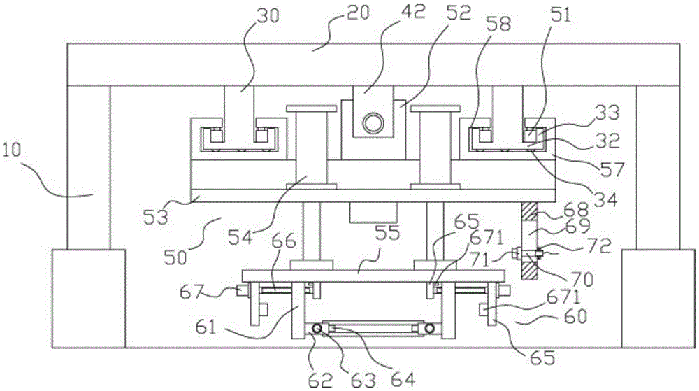
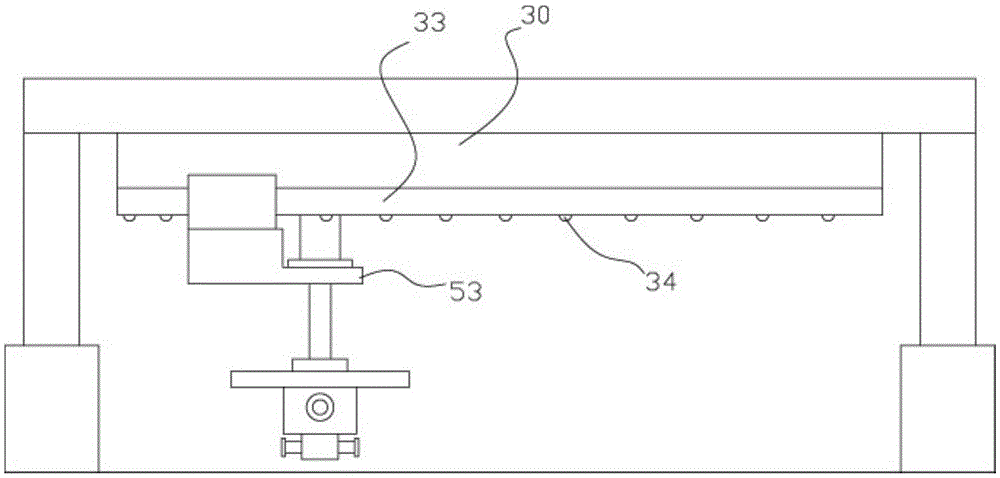
[0019] Example: see Figure 1 to Figure 5 As shown, a section steel automatic clamping and handling device includes a plurality of pillars 10, the tops of at least four pillars 10 are respectively fixed on the bottom surfaces of the four corners of the upper support plate 20, and the bottom ends of the pillars 10 are fixed on the ground , the left and right sides of the upper support plate 20 are fixed with two sliding track blocks 30, the upper support plate 20 between the two sliding track blocks 30 is provided with a transmission mechanism 40, and a sliding block 51 is installed on the mobile frame 50, and the sliding block 51 is on the sliding track block 30, and the middle part of the top surface of the mobile frame 50 is fixed with a connecting block 52, and the connecting block 52 is screwed in the transmission screw 41 of the transmission mechanism 40;

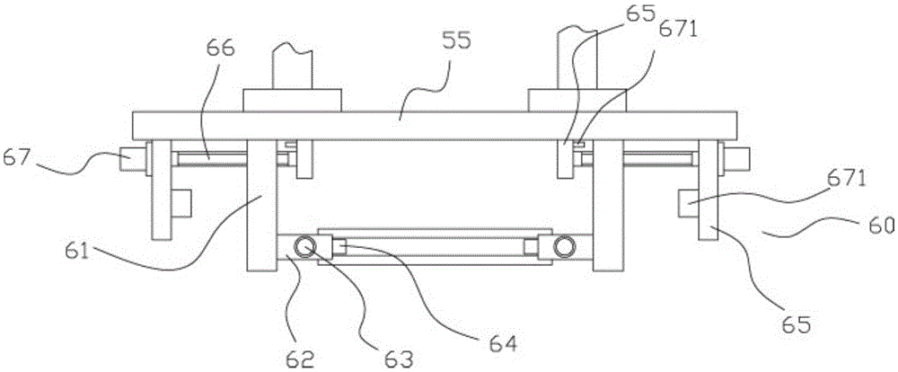
[0020] The front portion of the mobile frame 50 has an extension plate 53, and at least two push cylinders 54 are fi...


PUM


Abstract

The invention discloses an automatic clamping and conveying device for section steel. The automatic clamping and conveying device for the section steel comprises a plurality of supporting columns. The tops of at least four supporting columns are fixed to the bottom surfaces of the four corners of an upper supporting plate respectively. The bottom ends of the supporting columns are fixed on the ground. Two sliding track blocks are fixed to the left side and the right side of the upper supporting plate respectively. A transmission mechanism is arranged on the part, between the two sliding track blocks, of the upper supporting plate. Sliding blocks are mounted on a movable rack. The sliding blocks are located on the sliding track blocks. A connecting block is fixed to the middle of the top surface of the movable rack. The connecting block is in threaded connection with a transmission screw rod of the transmission mechanism. An extension plate is arranged at the front part of the movable rack. At least two pushing cylinders are fixed to the top surface of the extension plate. Push rods of the pushing cylinders vertically downwards penetrate through the extension plate and are fixed to a grabbing plate. Adjusting mechanisms are fixed to the two ends of the bottom surface of the grabbing plate respectively. Adjusting blocks are fixed to the adjusting mechanisms. The automatic clamping and conveying device for the section steel can convey the section steel quickly without professionals, and is safe in conveying.

Description

Technical field: [0001] The invention relates to the technical field of building material conveying equipment, in particular to an automatic clamping and conveying device for section steel. Background technique: [0002] Some existing shaped steels or I-beams are generally transported by cranes when they are transported, and when the crane is transported, it will shake the shaped steels and move them, which has potential safety hazards, and the operation of the cranes is cumbersome and requires professionals. operate. Invention content: [0003] The purpose of the present invention is to provide an automatic clamping and transporting device for section steel to address the deficiencies of the prior art, which can quickly transport section steel, and the transportation is fast, no professional personnel are needed, and the transportation is safe. [0004] Technical solutions of the present invention are as follows: [0005] An automatic clamping and handling device for se...

Claims


Application Information

Patent Timeline
Patent Type & Authority Applications(China)
IPC IPC(8): B65G47/90
CPCB65G47/90B66C1/22B66C1/445B66C9/14B66C15/00B66C19/00F16H25/20
Inventor 陈永林
Owner 天津冶建特种材料有限公司
Why Eureka
Try Eureka