Four-way material distributer free of material blocking

A distributor and material jamming technology, applied in the direction of transportation, packaging, loading/unloading, etc., can solve the problems of electro-hydraulic push rod overload, equipment failure, unreliability, etc., to expand the receiving caliber, prevent material leakage, and operate reliably Effect

Active Publication Date: 2016-05-04
WISDRI ENG & RES INC LTD
View PDF7 Cites 4 Cited by
  • Summary
  • Abstract
  • Description
  • Claims
  • Application Information

AI Technical Summary

Problems solved by technology

like figure 1 As shown, the existing four-way distributor includes a housing, two sets of electro-hydraulic push rods, a swing arm and a flap. The electro-hydraulic push rod drives the flap to rotate through the swing arm, and the two flaps cooperate with each other to realize three flow directions. However, the existing four-way feeder has the following problems: 1) The turnover plate is horizontal to the inside of the shell and there is a gap with the inner wall of the shell. In actual use, material leakage and jamming are easy to occur. Problems such as material loss and mixing will affect normal production, and material jams will lead to overload of the electro-hydraulic push rod, or failure to push the flap, and even cause serious equipment failures such as broken shafts of the flap; 2) Two sets of electro-hydraulic push rods, pendulum The arm and the flap need to be closely matched to complete the switching of the flow direction. When a problem or failure occurs in one group, the other group alone cannot complete the switching of the flow direction. Not only is the operation and maintenance complicated, the cost is high, and it is not reliable.

Method used


Image

  • Four-way material distributer free of material blocking
  • Four-way material distributer free of material blocking
  • Four-way material distributer free of material blocking

Examples


Embodiment Construction

[0024] The present invention will be further described below in conjunction with the drawings and embodiments.

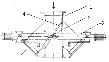
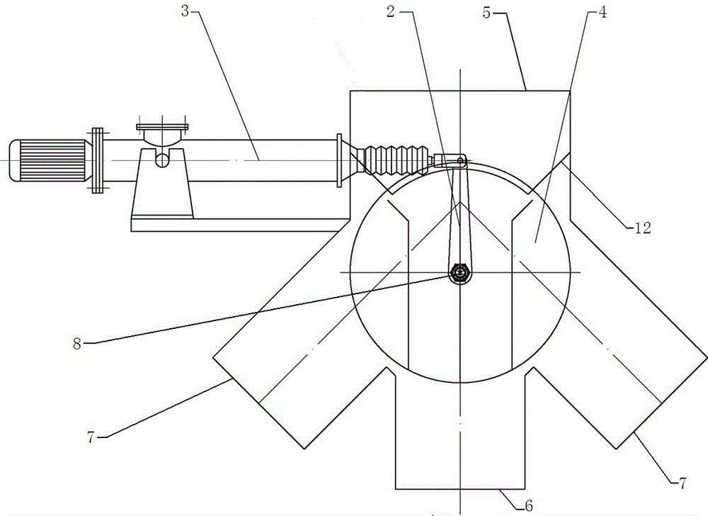
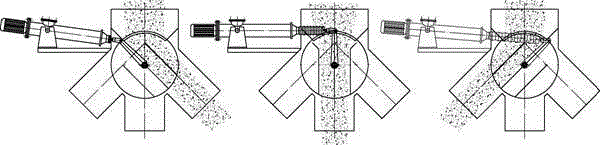
[0025] Such as figure 2 As shown, a non-jamming four-way distributor includes a housing 1, a vertical feed interface 5 is provided on the top of the housing 1, and a vertical discharge interface 5 is provided directly below the vertical feed interface 5 Interface 6, on both sides of the vertical discharging interface 6 are provided with two symmetrical oblique discharging interfaces 7 (when in use, the vertical feeding interface 5 is connected to an upstream conveying equipment through a flange, and the vertical discharging interface 6 And the two oblique discharging interfaces 7 are respectively connected to three downstream conveying equipment through flanges), the part where the vertical feeding interface 5, the vertical discharging interface 6 and the two inclined discharging interfaces 7 are combined is a cavity. The feature of the invention is that the four-way ...


PUM


Abstract

The invention relates to a four-way material distributer free of material blocking. A set of electric liquid pushing rods, a swing arm and an overturning plate are adopted for the four-way material distributer. The electric liquid pushing rods are arranged on a shell. The overturning plate is rotationally fixed in a cavity through a rotating shaft. One end of the swing arm is fixed to the rotating shaft, and the other end of the swing arm is hinged to the electric liquid pushing rods. The overturning plate comprises two parallel baffles and a plurality of partition plates vertically fixed between the baffles and parallel to each other. The two baffles are right opposite to the inner walls on the two sides of the cavity. A material collecting opening is formed in the bottom end of a vertical material inlet and always located between the two baffles. The overturning plate is made to rotate, materials are limited by the baffles and guided by the partition plates to enter a material discharge connector to which the partition plates point. The four-way material distributer effectively prevents the material clamping phenomenon, switching of three flow directions can be achieved through the set of electric liquid pushing rods, the swing arm and the overturning plate, cost is low, and operation is reliable.

Description

Technical field [0001] The invention relates to a bulk material conveying equipment, in particular to a four-way distributor without jamming. technical background [0002] The four-way distributor is a common equipment used to switch the direction of material flow during material transfer. It is generally used for working conditions where the upstream and downstream are connected to three channels and only one channel can be connected during bulk material transfer. Such as figure 1 As shown, the existing four-way distributor includes a shell and two sets of electro-hydraulic push rods, swing arms and flaps. The electro-hydraulic push rods drive the flaps to rotate through the swing arms. The two flaps cooperate with each other to achieve three flow directions. However, the existing four-way distributor has the following problems: 1) The flap is horizontal to the inside of the shell and there is a gap with the inner wall of the shell. In actual use, it is easy to leak and jam. Ca...

Claims


Application Information

Patent Timeline
Patent Type & Authority Applications(China)
IPC IPC(8): B65G65/40
CPCB65G65/40
Inventor 邓彪牛润芝鄢起红付秀芳
Owner WISDRI ENG & RES INC LTD
Why Eureka
Try Eureka