
Electroplating solution recovery device

A recovery device and electroplating device technology, applied in the electrolysis process, electrolysis components, cells, etc., can solve the problems of increased production costs, frequent parts replacement cycles, uneven force on the treatment container, etc., and achieve the effect of inhibiting the damage of small parts

Inactive Publication Date: 2013-01-02
扬州市金杨电镀设备有限公司
View PDF4 Cites 0 Cited by
  • Summary
  • Abstract
  • Description
  • Claims
  • Application Information

AI Technical Summary

Problems solved by technology

In this way, the production cost of the whole equipment will increase, and the use cost will also increase at the same time
[0011] ②The gasket is connected to the insulating bottom plate and the electrode ring through conductive screws. The gap between the electrode ring and the insulating bottom plate is different according to the screw tightening torque. During the rotation process, it is easy to cause uneven force on the processing container. It leads to the deformation of the insulating bottom plate. When the deformation is large enough, the entire processing container will be scrapped, and the cycle of replacing parts will be more frequent, which will increase the cost of use.

Method used


Image

  • Electroplating solution recovery device

Examples


Embodiment Construction

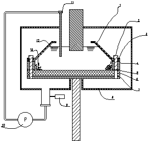
[0022] The processing container 1 of the present invention is formed by stacking the conductive plate 7 , the insulating plate 6 , the gasket 5 , the electrode ring 4 , and the upper cover 3 sequentially from the bottom, and connecting them with the conductive member 2 . When the electroplating liquid 12 needs to be discharged, the electroplating liquid 12 in the processing container 1 enters the recovery device 8 through the gap formed between the insulating plate 6 and the gasket 5, between the gasket 5 and the electrode ring 4, and starts and recovers the device 8 The connected vacuum device 9 makes a certain degree of vacuum formed in the recovery device 8 to realize the smooth discharge of the liquid medicine 12 .

[0023] The chemical solution of the present invention can realize the recycling of the chemical solution 12 through the pump 10, the circulation pipeline and the nozzle 11 connected to the lower part of the recovery device 8, and realize the cyclic electroplati...


PUM


Abstract

The invention relates to an electroplating solution recovery device arranged below a treatment container of an electroplating apparatus. The treatment container comprises an upper cover, an electrode ring, a gasket, an insulating plate and a conductive plate, which are sequentially connected from the top down via conductive pieces. The recovery device communicates with a gap formed among the electrode ring, the gasket and the insulating plate, and is provided thereon with an evacuation unit for forming vacuum in the recovery device. The recovery device can easily discharge electroplating solution, to improve electroplating quality of small parts, and prolong service life of the treatment container.

Description

technical field [0001] The invention relates to an electroplating solution recovery device, which is mainly suitable for electroplating of small parts such as powders with a thickness of 0.1 to 5000 microns, ultra-small capacitors, resistors, diodes, connectors, spring switches, nails, screws, nuts, washers, etc. Background technique [0002] figure 1 It is a schematic cross-sectional front view showing one of conventional small parts surface treatment apparatuses as shown in Patent Document 1. In this electroplating treatment apparatus, the processing container containing the small parts is rotated by a vertical rotation axis, the small parts are brought into contact with the electrode ring, and the electroplating chemical in the processing container is energized from the electrodes while circulating the electroplating chemical from the inside of the processing container to the outside. Thereby electroplating small parts. The processing container has an outflow mechanism ...

Claims


Application Information

Patent Timeline
IPC IPC(8): C25D17/16C25D21/18
Inventor 李俊周志慧陈德林任伟
Owner 扬州市金杨电镀设备有限公司
Learn More