
A special structure unloading device

A special structure, spiral plate technology, applied in the direction of transportation and packaging, conveyors, rotary conveyors, etc., can solve the problems of discontinuous feeding, poor uniformity, easy material jams, etc., to improve feeding efficiency and ensure continuous The effect of sex and uniformity

Active Publication Date: 2018-04-20
GUIYANG AL-MG DESIGN & RES INST
View PDF11 Cites 0 Cited by
  • Summary
  • Abstract
  • Description
  • Claims
  • Application Information

AI Technical Summary

Problems solved by technology

[0002] In the fields of industry, agriculture, metallurgy, etc., many raw materials, finished products, and semi-finished products exist in the form of granules or powders. The traditional feeding methods, such as turning board blanking, etc., for such granular or powdered materials, the total There are disadvantages such as discontinuous feeding, poor uniformity and easy material jams.

Method used


Image

  • A special structure unloading device
  • A special structure unloading device

Examples


Embodiment Construction

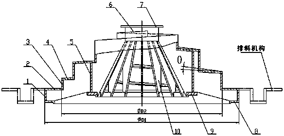
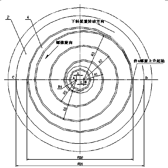
[0018] like figure 1 and figure 2 As shown in the figure, a special structure blanking device includes a first steel plate 8, a second steel plate 9, a steel pipe 6 and a third steel plate 7 arranged in sequence from bottom to top. The top of the first steel plate 8 is connected to the first side plate 1, The upper end of one side plate 1 is the annular plane 2, the upper end of the annular plane 2 is the second side plate 3, the second side plate 3 is connected with the spiral plate 4, and the spiral plate 4 includes the first spiral plate part on both sides of the diameter CD of the annular plane 2 and The second spiral plate part, the first spiral plate part includes three spirals with the same rotation center (both point B), and the rotation center is located on the diameter CD of the annular plane 2, and is far from the center L of the annular plane 2 (the center is to the right) Steel plates, the helical radii of the three spiral steel plates are R1, R2 and R3 respecti...


PUM


Abstract

The invention discloses a special structure laying-off device, comprising an annular plane (2), a spiral plate (4) which is on the annular plane (2) and rises in a spiral manner along an anticlockwise direction, and side plates on the outer sides of the annular plane (2) and the spiral plate (4). When the laying-off device rotates, the side surface of a spiral cone would generate outward thrust on peripheral materials. Under the action of thrust, material particles or powders in good mobility would continuously uniformly drop to the periphery along a spiral surface, and finally enter a discharge mechanism. Compared with flip laying-off and other conventional laying-off methods, the spiral cone structure laying-off is advantaged by continuous, uniform, and no material stuck.

Description

technical field [0001] The invention relates to a feeding device, which is used for feeding in a container, and the feeding material is granular or powder with certain fluidity. Background technique [0002] In the fields of industry, agriculture, metallurgy, etc., many raw materials, finished products, and semi-finished products exist in the form of granules or powder. Traditional cutting methods, such as turning plate cutting, etc. There are disadvantages such as discontinuous cutting, poor uniformity and easy jamming. SUMMARY OF THE INVENTION [0003] The technical problem to be solved by the present invention is: to provide a special structure blanking device, which can prevent the phenomenon of jamming when blanking granular or powdery materials, ensure the continuity and uniformity of blanking, and improve blanking efficiency. [0004] The technical scheme of the present invention is as follows: a special structure blanking device comprises an annular plane, the upp...

Claims


Application Information

Patent Timeline
Patent Type & Authority Patents(China)
IPC IPC(8): B65G29/02
Inventor 陈进勇
Owner GUIYANG AL-MG DESIGN & RES INST
Learn More