Method for removing dirt on surface of trash rack in narrow trash rack hole

A trash rack and orifice technology, applied to mechanically driven excavators/dredgers, etc., can solve problems such as low efficiency, shutdown cleaning, poor safety, etc.

Active Publication Date: 2016-05-04
郑州华林清污起重设备有限公司
View PDF4 Cites 6 Cited by
  • Summary
  • Abstract
  • Description
  • Claims
  • Application Information

AI Technical Summary

Problems solved by technology

However, for the removal of dirt on the surface of the trash rack in some narrow trash rack openings, the narrow opening cannot accommodate the width of the cleaning bucket or the width of the movable pulley for lifting the cleaning bucket, so that the cleaning work cannot be carried out normally.
In the prior art, this kind of narrow trash rack opening is usually manually cleaned or the narrow and small dirt grab bucket with small bucket capacity is used to remove the dirt on the grid surface of the trash rack. The method is inefficient, high in cost, poor in safety, and often needs to be shut down for cleaning, which affects the normal operation of the hydroelectric generating set or pumping station

Method used


Image

  • Method for removing dirt on surface of trash rack in narrow trash rack hole
  • Method for removing dirt on surface of trash rack in narrow trash rack hole
  • Method for removing dirt on surface of trash rack in narrow trash rack hole

Examples


Embodiment Construction

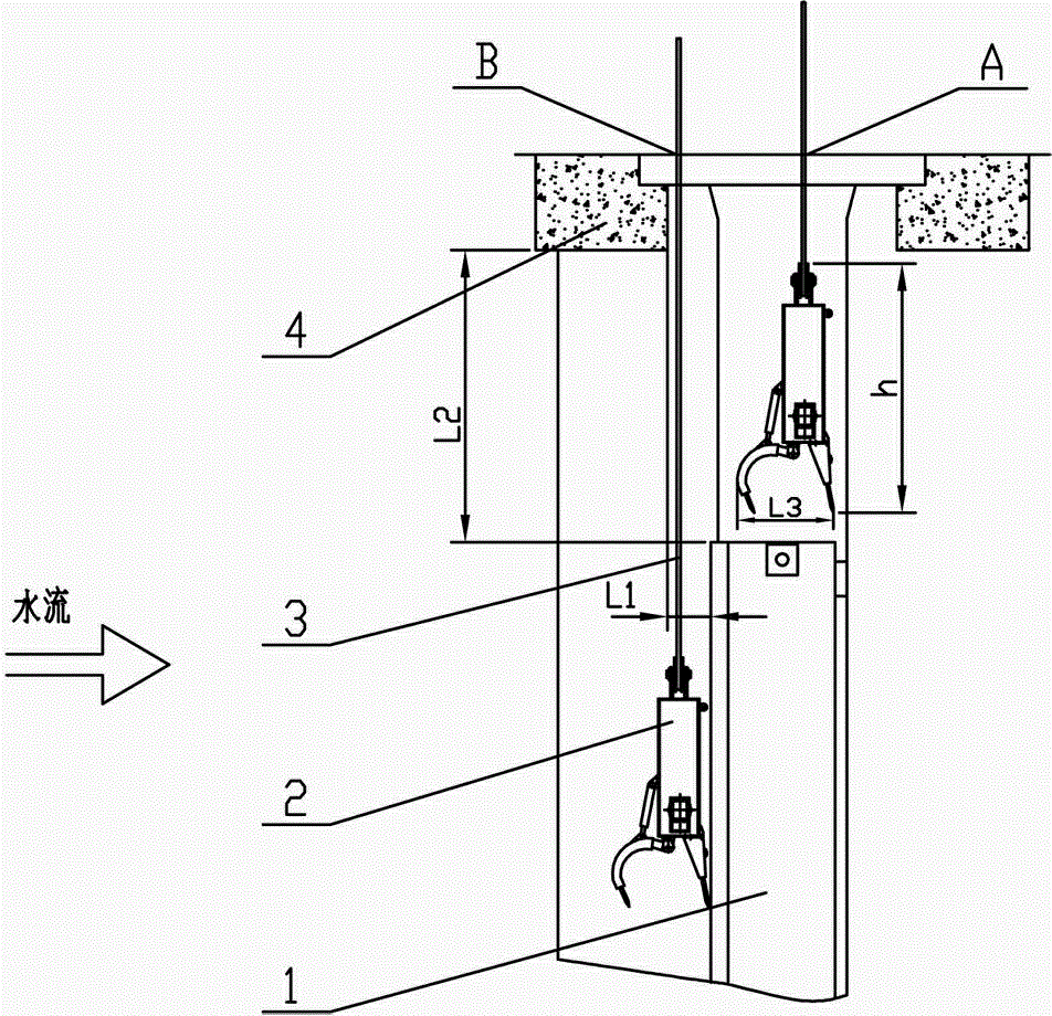
[0032] figure 1 It is an explanatory diagram for the applicable occasions of the method for removing dirt from the trash rack surface in the narrow trash rack aperture of the present invention, in which the horizontal distance from the grid surface of the trash rack 1 to the hydraulic structure 4 at the aperture is L1, the vertical distance from the top surface of the trash rack 1 to the bottom surface of the orifice hydraulic structure 4 is L2; ​​the width of the cleaning grab 2 in the figure is L3, and the height of the cleaning grab 2 is h. For the orifice of this narrow trash rack, since the horizontal distance L1 from the grid surface of the trash rack to the hydraulic structure at the orifice is generally smaller than the width L3 of the cleaning grab, the cleaning grab cannot The method is to directly go down to the grid surface of the trash rack to carry out the cleaning work. But if the height dimension h of this cleaning bucket is less than the top surface of the tr...


PUM


Abstract

The invention discloses a method for removing dirt on the surface of a trash rack in a narrow trash rack hole. The method can solve the problem of interference of the narrow trash rack hole on a dirt removal grab bucket or a movable pulley or a steel wire rope connected to the dirt removal grab bucket, can efficiently carry out the operation of removing the dirt on the surface of the trash rack in the narrow trash rack hole, and is applicable to places in which the height of the dirt removal grab bucket is smaller than the height from the bottom surface of a hydraulic structure of upstream side hole of the trash rack to the top surface of the trash rack. The method comprises the following steps: setting the rate of a pulley block of a lifting mechanism of a lifting dirt removal grab bucket (2) as 1, namely directly connecting a steel wire rope (3) of the lifting mechanism to the dirt removal grab bucket (2), dropping the dirt removal grab bucket (2) to the top of the trash rack (1), then moving the dirt removal grab bucket (2) from a position A at the top of the trash rack to an edge B of the hydraulic structure (4) near the upstream side of the trash rack along the water flowing direction, then dropping the dirt removal grab bucket (2) to the surface of the trash rack (1) and carrying out the dirt removal operation; then extracting the dirt grabbed by the dirt removal grab bucket (2) in an opposite order, and carrying out the operation of removing the dirt on the surface of the trash rack (1).

Description

technical field [0001] The invention belongs to a method for cleaning trash racks at water inlets of hydro turbines in power stations or water diversions in pumping stations. Specifically, it is a method to remove the dirt on the surface of the trash rack in the narrow trash rack opening. Background technique [0002] Trash racks are generally installed in front of the water inlets of hydroelectric generating units or pumping stations of hydropower stations. The dirt attached to the front of the trash racks and the surface of the trash racks needs to be removed to ensure the smooth flow of water. However, for the removal of dirt on the surface of the trash rack in some narrow trash rack openings, the narrow opening cannot accommodate the width of the cleaning bucket or the width of the movable pulley for lifting the cleaning bucket, so that the cleaning work cannot be carried out normally. . In the prior art, this kind of narrow trash rack opening is usually manually clean...

Claims


Application Information

Patent Timeline
Patent Type & Authority Applications(China)
IPC IPC(8): E02F3/47E02F3/50
Inventor 吕燕林王奋追盛戈董永霞田盈辉李新亚
Owner 郑州华林清污起重设备有限公司
Why Eureka
Try Eureka