Three-wire hanging support

A three-wire hanging and crossbeam technology, which is applied in the direction of cable suspension devices and cable space arrangement/configuration, can solve problems such as damaging the load balance of power lines, overloading poles, threatening the safety of power supply equipment, and people's lives and property. Easy maintenance and clear lines

Inactive Publication Date: 2016-05-04
LISHUI POWER SUPPLY COMPANY OF STATE GRID ZHEJIANG ELECTRIC POWER +2
View PDF8 Cites 4 Cited by
  • Summary
  • Abstract
  • Description
  • Claims
  • Application Information

AI Technical Summary

Problems solved by technology

These cables that are not hung according to the regulations destroy the load balance of the power line, causing the poles to be "overloaded". and major hidden dangers to the lives and property of the people
At the same time, it also has a great impact on the safe operation of power lines and operation and maintenance personnel's work on poles, and has become a hidden danger in power safety production.

Method used


Image

  • Three-wire hanging support
  • Three-wire hanging support
  • Three-wire hanging support

Examples


Embodiment 1

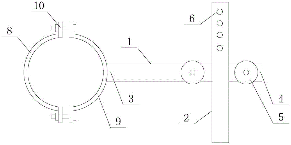
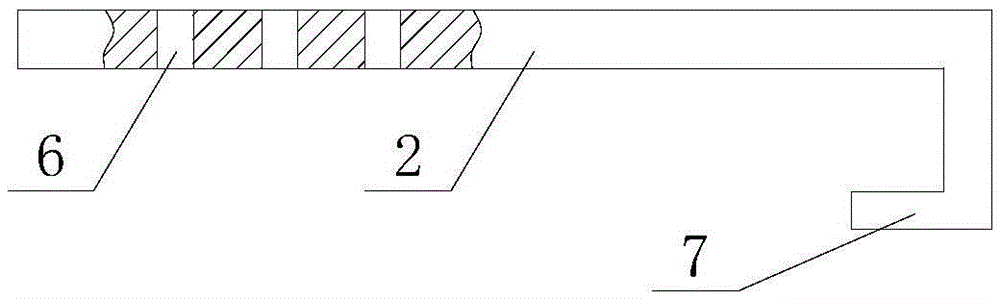
[0013] refer to figure 1 , figure 2 It is an embodiment of a three-wire hanging bracket of the present invention. A three-wire hanging bracket includes a beam 1, a longitudinal beam 2 and a fixing device connected to an electric pole. The beam 1 includes a fixed end 3 and a connecting end 4. The fixed end 3 of the beam 1 is connected with the fixing device, the longitudinal beam 2 is vertically welded on the connection end 4 of the beam 1, and the beam 1 on both sides of the longitudinal beam 2 is also fixed with an insulator 5, and the longitudinal beam 2 A number of connection holes 6 are arranged on the top, and a hook 7 is also arranged at one end of the longitudinal beam 2 .

[0014] The fixing device comprises a left half-wrap 8 and a right half-wrap 9, the cross section of the left half-wrap 8 is arc-shaped and the corresponding central angle is less than 180 degrees, and the two ends of the left half-wrap 8 are respectively provided with a The lug 10 and the lug 10 ...

Embodiment 2

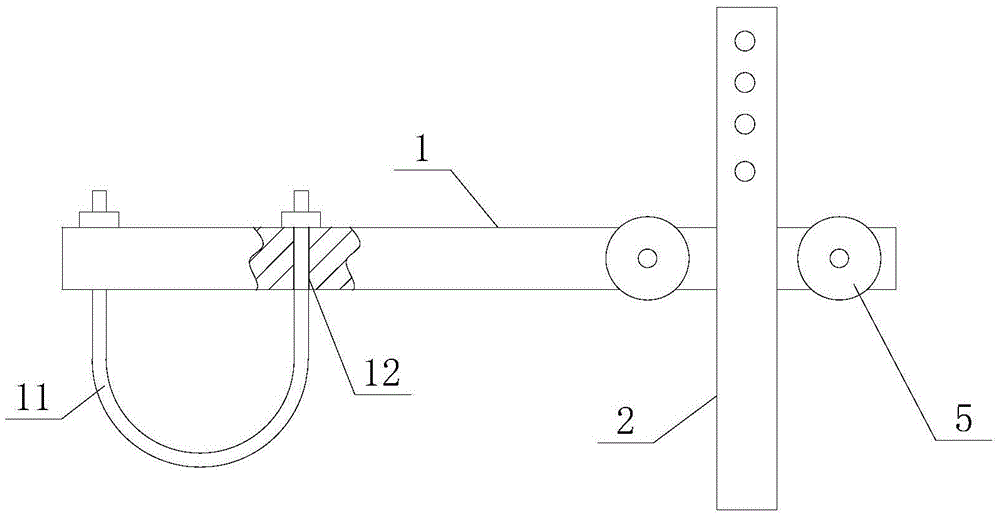
[0017] Such as image 3 As shown, the difference from Embodiment 1 is that the fixing device is different. The fixing device is a connecting rod 11 with a U-shaped cross section. Both ends of the connecting rod 11 are provided with threads. There are two through holes 12 , and the distance between the two through holes 12 is equal to the distance between the two ends of the connecting rod 11 .

[0018] Hold the electric pole through the connecting rod 11, the two ends of the connecting rod 11 pass through the corresponding through holes 12, and then tighten the nuts so that the beam 1 and the connecting rod 11 cooperate to hold the electric pole tightly, thereby fixing the pole on the electric pole position on the

[0019] After using the device, the power line is connected by the insulator 5, and the communication line and the radio and television line are respectively hung on the two ends of the longitudinal beam 2, and the connection hole 6 and the hook 7 are pre-opened on...


PUM


Abstract

The invention discloses a three-line hanging support. The three-line hanging support comprises a cross beam, a longitudinal beam and a fixing device connected with an electric rod. The cross beam comprises a fixed end and a connection end. The fixed end of the cross beam is connected with the fixing device. The longitudinal beam is perpendicularly fixed to the connection end of the cross beam. Insulators are further fixed on the cross beam on two sides of the longitudinal beam. The three-line hanging support has the advantages that after the device is used, an electric power line is connected with the insulators, a communication line and a broadcast television line are respectively hung on two ends of the longitudinal beam, the longitudinal beam is arranged to facilitate the fixing of lines and the installation of an equipment box; in addition, after the device is used, the lines on the electric rod are very clear, the electric power line, the television line and the communication line are separated from each other, a worker is no longer distributed by the lines when climbing the electric rod, and the line maintenance is convenient.

Description

technical field [0001] The invention relates to a three-wire hanging bracket. Background technique [0002] In recent years, the "three-wire" phenomenon formed by communication lines, radio and television lines, and network lines has been around for a long time. These cables that are not hung according to the regulations destroy the load balance of the power line, causing the poles to be "overloaded". and a major hidden danger to the lives and property of the people. At the same time, it also has a great impact on the safe operation of power lines and the operations of operation and maintenance personnel on poles, and has become a hidden danger in electric power production safety. Contents of the invention [0003] The purpose of the present invention is to provide a three-wire hanging bracket, which can effectively solve the problem that the mixed connection of three wires on the existing electric pole seriously threatens the safety of power supply equipment. [0004] ...

Claims


Application Information

Patent Timeline
Patent Type & Authority Applications(China)
IPC IPC(8): H02G7/05H02G7/20
Inventor 徐永礼吴建勇刘建宇陈军邓硕李仁贤王存美王存平刘丽玲
Owner LISHUI POWER SUPPLY COMPANY OF STATE GRID ZHEJIANG ELECTRIC POWER
Why Eureka
Try Eureka