
Imaging apparatuses and a time of flight imaging method

A time-of-flight and imaging device technology that is applied to measuring devices, image communications, instruments, etc., and can solve problems such as increasing costs

Active Publication Date: 2016-05-04
INFINEON TECH AG
View PDF3 Cites 6 Cited by
  • Summary
  • Abstract
  • Description
  • Claims
  • Application Information

AI Technical Summary

Problems solved by technology

This may result in high or increased costs, for example

Method used


Image

  • Imaging apparatuses and a time of flight imaging method
  • Imaging apparatuses and a time of flight imaging method
  • Imaging apparatuses and a time of flight imaging method

Examples


Embodiment Construction

[0013] Various example embodiments will now be described more fully with reference to the accompanying drawings, in which some example embodiments are illustrated. In the drawings, the thickness of lines, the thickness of layers and / or regions may be exaggerated for clarity.

[0014] Therefore, while the example embodiments are capable of various modifications and alternative forms, embodiments thereof are shown in the drawings by way of example and will be described herein in detail. It should be understood, however, that there is no intent to limit example embodiments to the particular forms disclosed, but on the contrary, example embodiments are to cover all modifications, equivalents, and alternatives falling within the scope of the disclosure. . Like numbers refer to the same or similar elements throughout the description of the figures.

[0015] It will be understood that when an element is referred to as being "connected" or "coupled" to another element, it can be dir...


PUM


Abstract

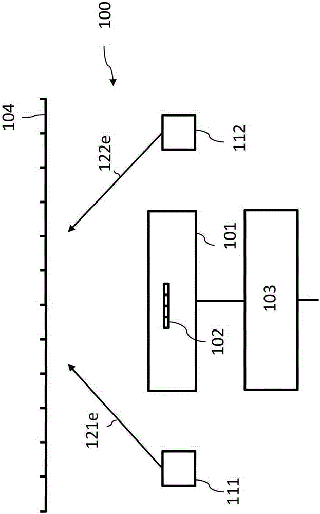
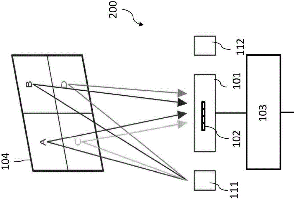
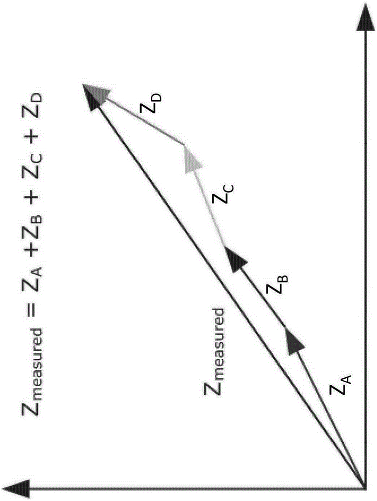
The imaging apparatus includes an image sensor circuit comprising a time of flight sensor pixel. The imaging apparatus further includes a first light emitter having a first spatial offset relative to the time of flight sensor pixel. The imaging apparatus further includes a second light emitter having a second spatial offset relative to the time of flight sensor pixel. The imaging apparatus further includes an image processing circuit configured to produce an image of a region of an object based on first sensor pixel image data and second sensor pixel image data generated by the time of flight sensor pixel. The first sensor pixel image data is based on received light emitted by the first light emitter and reflected at the object's region and wherein the second sensor pixel image data is based on received light emitted by the second light emitter and reflected at the object's region.

Description

technical field [0001] Embodiments relate to generating three-dimensional images, and in particular, to imaging devices and time-of-flight imaging methods. Background technique [0002] Time-of-flight (TOF) systems are based on the principle of three-dimensional (3D) image sensors. For example, pixels may be more complex than those of a two-dimensional (2D) imager. For example, pixels can be larger. For example, high-resolution imagers may require large chip areas, large optics, and bulky cameras. For example, this may result in high or increased costs. Contents of the invention [0003] Some embodiments relate to imaging devices. The imaging device includes image sensor circuitry including time-of-flight sensor pixels. The imaging device further includes a first light emitter having a first spatial offset relative to the time-of-flight sensor pixels. The imaging device further includes a second light emitter having a second spatial offset relative to the time-of-fli...

Claims


Application Information

Patent Timeline
IPC IPC(8): H04N5/335H04N5/232G01S7/4863G01S7/4865G01S17/894
CPCG01S17/08G01S7/4815G01S7/4863G01S7/4865G01S7/499G01S17/894H04N13/254
Inventor M·戴拉彻M·弗拉斯彻M·马克J·普莱恩萨克
Owner INFINEON TECH AG
Learn More