Headset interface conversion device and electronic equipment

A conversion device and headphone interface technology, applied in transducer circuits, handset/headphone accessories, electrical components, etc., can solve problems such as incompatibility between audio-visual equipment and headphones, improve user experience, avoid waste of resources, and be easy to use Effect

Inactive Publication Date: 2016-05-04
WEIFANG GOERTEK ELECTRONICS CO LTD
View PDF14 Cites 2 Cited by
  • Summary
  • Abstract
  • Description
  • Claims
  • Application Information

AI Technical Summary

Problems solved by technology

[0004] The present invention provides an earphone interface conversion device, which solves the problem of incompatibility between audio-visual equipment and earphones

Method used


Image

  • Headset interface conversion device and electronic equipment
  • Headset interface conversion device and electronic equipment
  • Headset interface conversion device and electronic equipment

Examples


Embodiment 1

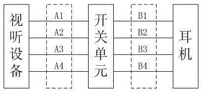
[0023] Embodiment 1. The headphone interface conversion device of this embodiment mainly includes a first interface group A, a second interface group B, a switch unit, etc., the first interface group A is connected to the second interface group B through the switch unit; the first interface group A includes the left channel interface A1, the right channel interface A2, the microphone interface A3, and the ground interface A4, and the second interface group B includes the left channel interface B1, the right channel interface B2, the microphone interface B3, and the ground interface B4. see figure 1 shown.

[0024] The left channel interface A1 of the first interface group A is respectively connected to the left channel interface B1, the right channel interface B2, the microphone interface B3, and the ground interface B4 of the second interface group B through a switch unit, and the switch unit controls A1 and B1 , B2, B3, and B4 connection lines; the right channel interface A...

Embodiment 2

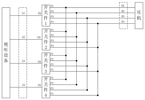
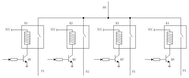
[0052] Embodiment 2. The difference between the headphone jack conversion device of this embodiment and Embodiment 1 is that the structural design of the switch unit of the switch unit is different. In this embodiment, each switch unit of the switch unit is a four-way switch. The four-way switch includes a toggle block, a common pin P0, a first pin P1, a second pin P2, a third pin P3, and a fourth pin P4, and the toggle block of the switch is toggled in four directions, so that the common The pin P0 can be connected to any one of the first pin P1, the second pin P2, the third pin P3, and the fourth pin P4, see Figure 4 shown.

[0053] see Figure 4 As shown, move the switch up, the connection line between P0 and P1 is turned on; move the switch to the right, the connection line between P0 and P2 is turned on; move the switch down, the connection line between P0 and P3 is turned on; Toggle the switch to the left, and the connection line between P0 and P4 is turned on.

[00...


PUM


Abstract

The invention discloses a headset interface conversion device and electronic equipment. The device comprises a first interface group, a second interface group and a switch unit, and each of the first interface group and the second interface group includes a left channel interface, a right channel interface, a mike interface and a ground wire interface; the left channel interface of the first interface group is connected with the four interfaces of the second interface group through the switch unit, the right channel interface of the first interface group is connected with the four interfaces of the second interface group through the switch unit, the mike interface of the first interface group is connected with the four interfaces of the second interface group through the switch unit, the ground wire interface of the first interface group is connected with the four interfaces of the second interface group through the switch unit, and the switch unit controls on-off of a connecting circuit. The headset interface conversion device and electronic equipment provided by the invention realize mutual compatibility of audio-visual equipment and a headset, thereby enabling the audio-visual equipment to communicate with the headset normally; and use of a user is facilitated, usage cost is reduced, and resource waste is avoided.

Description

technical field [0001] The invention belongs to the technical field of earphone jacks, and in particular relates to an earphone jack conversion device and electronic equipment designed using the earphone jack conversion device. Background technique [0002] Many current audio-visual products and smart products have headphone jacks for listening to songs and watching videos, and some also have a voice input microphone function. [0003] However, the current headphone design is not compatible with audio-visual products. It is often encountered: there is no sound when the earphone is fully inserted into the device, but there is sound when the earphone is not fully inserted; there is sound after the earphone is fully inserted, but the voice function cannot be realized; no matter No matter how you plug it in, you can’t satisfy the situation of having sound and voice at the same time. You can only re-match another earphone according to the device, which is inconvenient for users a...

Claims


Application Information

Patent Timeline
Patent Type & Authority Applications(China)
IPC IPC(8): H04R1/10H04R3/00
CPCH04R1/10H04R3/00
Inventor 刘家君
Owner WEIFANG GOERTEK ELECTRONICS CO LTD
Why Eureka
Try Eureka