Gas discharge lamp and use thereof

A gas discharge lamp, gas technology, applied in the field of deuterium lamps, can solve the problem of reducing lamp life

Inactive Publication Date: 2016-05-04
HERAEUS NOBLELIGHT LTD
View PDF4 Cites 0 Cited by
  • Summary
  • Abstract
  • Description
  • Claims
  • Application Information

AI Technical Summary

Problems solved by technology

There occurs a change in the glass of the bulb, which causes light absorption and scattering and thus significantly reduces the life of the lamp

Method used


Image

  • Gas discharge lamp and use thereof
  • Gas discharge lamp and use thereof
  • Gas discharge lamp and use thereof

Examples


Embodiment Construction

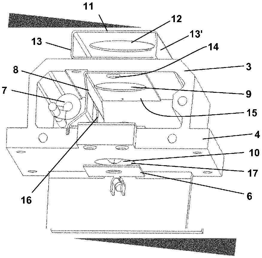
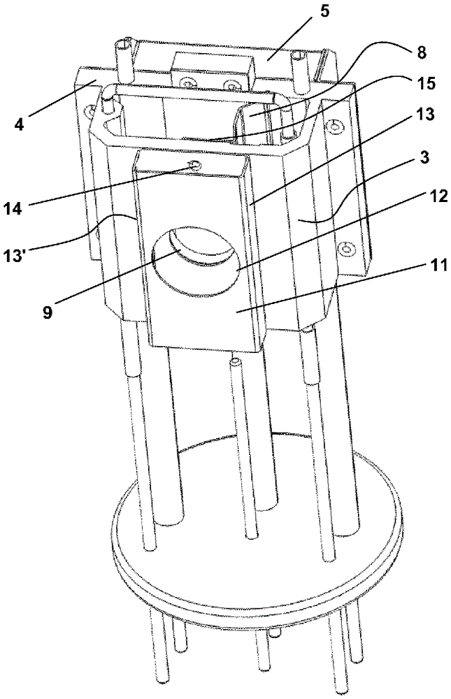
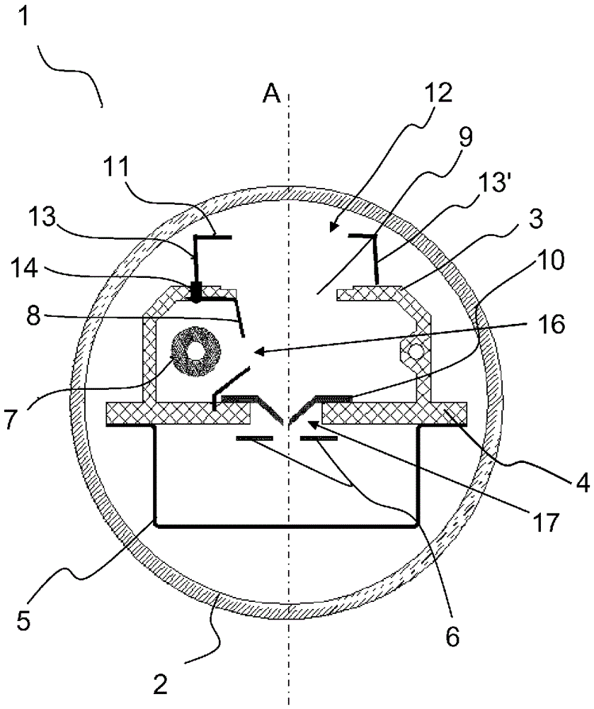
[0031] exist figure 1 , schematically shows a cross-section of a deuterium lamp 1 along the optical axis A. The lamp 1 has a bulb 2 and a two-part housing consisting of a front housing part 3 with a housing intermediate wall 4 and a rear housing part 5 which The housing part is made of ceramic, in this case aluminum oxide, and the rear housing part is made of metal. The bulb 2 is filled with a gas, here deuterium. The anode 6 is located in the rear housing part 5 . A cathode 7 and a cathode shielding window 8 made of nickel sheet metal are arranged in the front housing part 3 . Furthermore, the front housing part 3 has a light exit window 9 which is situated opposite the anode 6 and forms with it the optical axis A of the gas discharge lamp. The cathode shielding window 8 has an opening 16 in the direction of the optical axis A. As shown in FIG. When the lamp 1 is in operation, a discharge is formed between the cathode 7 and the anode 6, which discharge provides a contin...


PUM


Abstract

The invention relates to gas discharge lamps, in particular deuterium lamps, with a lamp bulb (2) filled with gas, comprising: an electrode housing with a front housing part (3) made of a non-electrically conductive material, a rear housing part (5), and a housing partition (4) which separates the front housing part (3) from the rear housing part (5). The front housing part (3) has a cathode (7), a cathode shielding window (8) arranged in front of the cathode (7), and a light outlet window (9) which emits light caused by the discharge towards the outside, and the rear housing part (5) receives an anode (6) which lies in the front housing part (3) on an optical axis A together with the light outlet window (9). The gas discharge lamp is characterized in that an outlet diaphragm (11) which has an adjustable electric potential and comprises a diaphragm opening (12) is arranged on the outside in front of the light outlet window (9), said diaphragm opening (12) lying on the optical axis A in projection of the light outlet window (9) and being spaced from said window. Damage to the lamp bulb material can be prevented by the outlet diaphragm. The invention further relates to the use of such gas discharge lamps for analytical purposes.

Description

technical field [0001] The invention relates to a gas discharge lamp, in particular a deuterium lamp, with a gas-filled bulb and an arrangement in the bulb, comprising: an electrode housing with a front housing made of a non-conductive material part, a rear housing part and a housing partition separating the front housing part from the rear housing part, wherein the front housing part comprises a cathode arranged in the a cathode shielding window in front of the cathode and a light exit window which emits light caused by the discharge outward, and wherein the rear housing part houses an anode which is connected to the front housing part The light exit window in is located on the optical axis A. [0002] Furthermore, the invention relates to the use of gas discharge lamps for analytical purposes. Background technique [0003] Gas discharge lamps are used as light sources for generating optical radiation in the visible, ultraviolet or infrared range. The gas discharge lamp ...

Claims


Application Information

Patent Timeline
Patent Type & Authority Applications(China)
IPC IPC(8): H01J61/10H01J61/68
CPCH01J61/10H01J61/68
Inventor E.阿尔诺德C.泽勒I.拉多塞维奇A.施纳布尔G.德辛格T.耶内克G.佩尔莱特N.菲舍尔G.达马施克T.施奈德B.于宾
Owner HERAEUS NOBLELIGHT LTD
Why Eureka
Try Eureka